Three-point hitch faceplate

a three-point hitch and faceplate technology, applied in mechanical machines/dredgers, agricultural machines, transportation and packaging, etc., can solve the problems of compact skid steer machines, lack of steerable wheels, and high price of skid steer machines, and the equipment used with skid steer machines is specialized

Inactive Publication Date: 2006-09-19
THOR INTERTECH LLC
View PDF21 Cites 29 Cited by
  • Summary
  • Abstract
  • Description
  • Claims
  • Application Information

AI Technical Summary

Problems solved by technology

The skid steer machines are compact and lack any steerable wheels.
One of the disadvantages of the skid steer machines is that the skid steer machines are relatively expensive and the equipment used with the skid steer machi

Method used


Image

  • Three-point hitch faceplate
  • Three-point hitch faceplate
  • Three-point hitch faceplate

Examples


Embodiment Construction

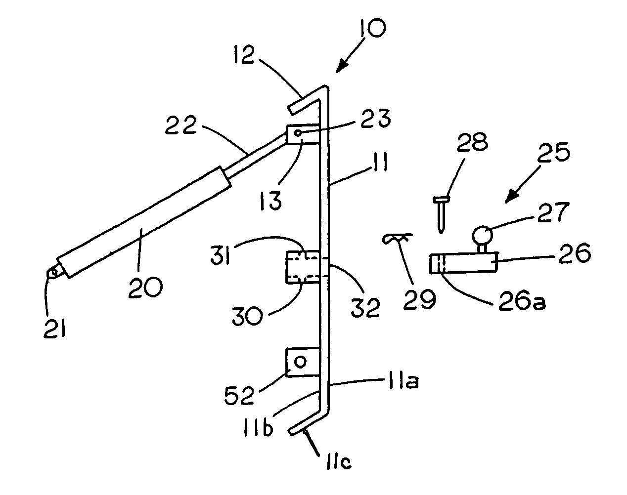
[0041]FIG. 1 shows a side view of the three-point hitch faceplate 10 and FIG. 5 shows a rear view of the three-point hitch faceplate 10, which is made of metal. The three-point hitch faceplate 10 comprises a rigid rectangular shaped member 11 having a front face 11a, a rear face 11b and a rearward extending top lip 12 to form mating engagement with a conventional skid steer attachment and a bottom angled lip 11c that engages a locking mechanism to hold an attachment on the three-point hitch faceplate 10. Mounted on the rear face 11b of faceplate 11 is a first connecting member 52 and a second connecting member 50 with connecting members 52 and 50 laterally spaced from each other and secured to the back side 11b of rigid member 11. The first connecting member 52 is connectable to a first tractor mount (not shown) through a pin 53 and the second connecting member 50 is connectable to a second tractor mount (not shown) through a pin 51. A third connecting member 13 is secured to the ba...


PUM


Abstract

A three-point hitch faceplate having a set of skid steer receiver attachment points to permit an all-purpose agricultural tractor to operably connect to skid steer attachments so that the agricultural tractor can utilize off-the-shelf skid steer attachments.

Description

CROSS REFERENCE TO RELATED APPLICATIONS[0001]This application claims priority from my provisional application 60 / 437,076 filed Dec. 30, 2002 titled Three-point hitch faceplate.FIELD OF THE INVENTION[0002]This invention relates generally to apparatus to allow a user to use specialty equipment available for skid steer loaders on a conventional vehicle such as an agricultural tractor with a three-point hitch.STATEMENT REGARDING FEDERALLY SPONSORED RESEARCH OR DEVELOPMENT[0003]NoneREFERENCE TO A MICROFICHE APPENDIX[0004]NoneBACKGROUND OF THE INVENTION[0005]Skid steer machines are known and widely used for many tasks. The skid steer machines are compact and lack any steerable wheels. In contrast to machines that have steerable wheels the skid steer maneuvers by stopping or slowing the rotation of one set of side wheels while allowing the other set of side wheels to rotate. The skid steer machines are extremely popular for use in special operations. As a result, a number of different atta...

Claims


Application Information

Patent Timeline
IPC IPC(8): E02F9/00
CPCA01B59/062A01D87/122E02F9/006E02F3/3604B60D1/07
Inventor GUSTAFSON, JOHN
Owner THOR INTERTECH LLC
Why Eureka
Try Eureka