Power connector

a technology of power connectors and connectors, applied in the direction of coupling device connections, coupling protection earth/shielding arrangements, securing/insulating coupling contact members, etc., can solve the problems of increasing resistance, unsteady transmission of voltage, and complicating the assembly process, so as to achieve simple design

Active Publication Date: 2006-09-19
HON HAI PRECISION IND CO LTD
View PDF5 Cites 86 Cited by
  • Summary
  • Abstract
  • Description
  • Claims
  • Application Information

AI Technical Summary

Benefits of technology

[0010]A second object of the present invention is to provide a power connector of a simple design.

Problems solved by technology

However, in such case, when the complementary connector is inserted into the power connector, the pushing force will make the central contact be pushed backward away from the housing, then cause the unreliable engagement between the central contact and the terminal of the complementary connector leading unsteadily transmitting of the voltage.
However, such a way transmitting the voltage by transferring it from another terminal to the conductive pin increases the resistance.
However, such a securing method increases an additional component, also complicates the assemble process.

Method used


Image

  • Power connector
  • Power connector
  • Power connector

Examples


Embodiment Construction

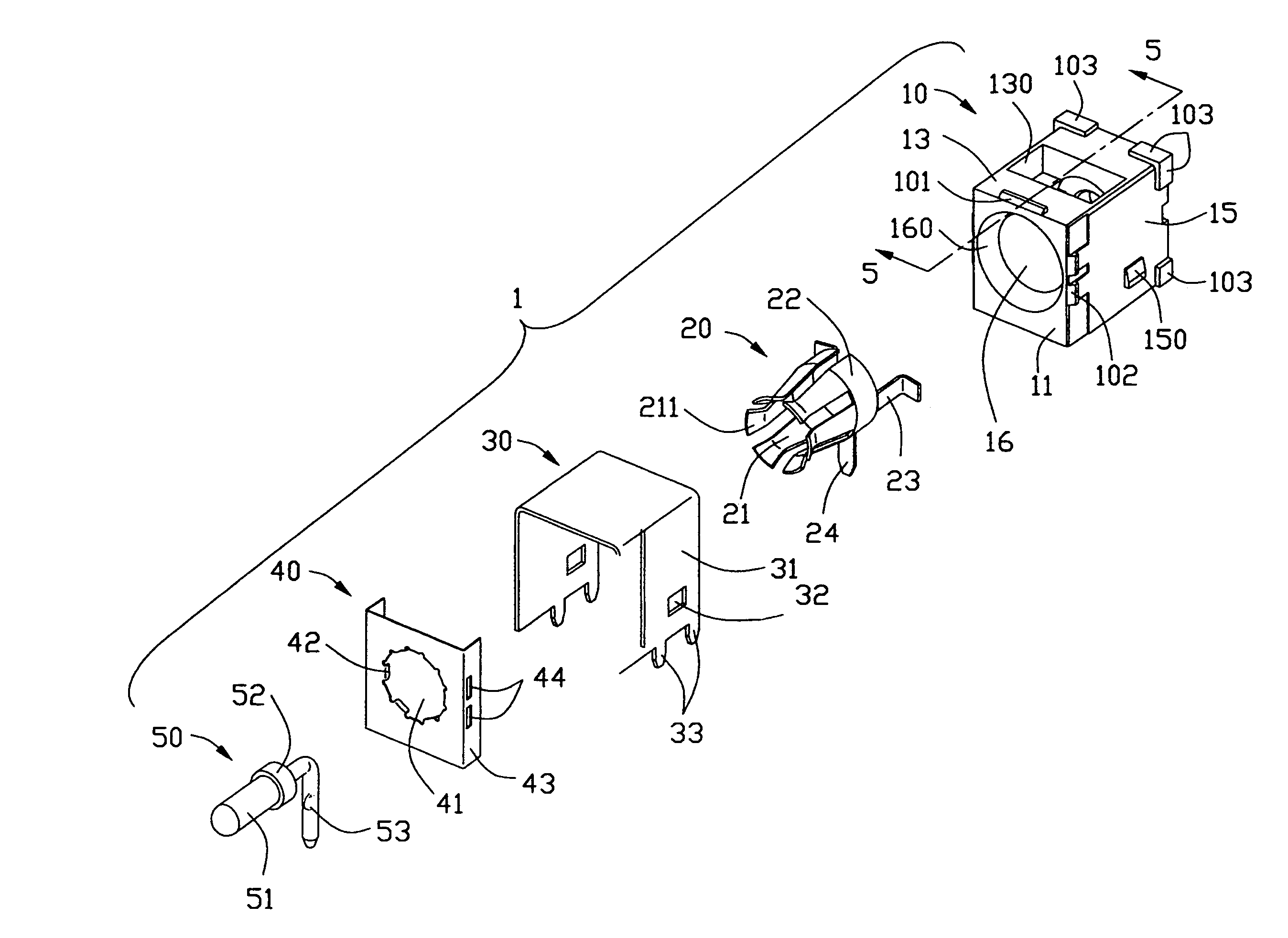
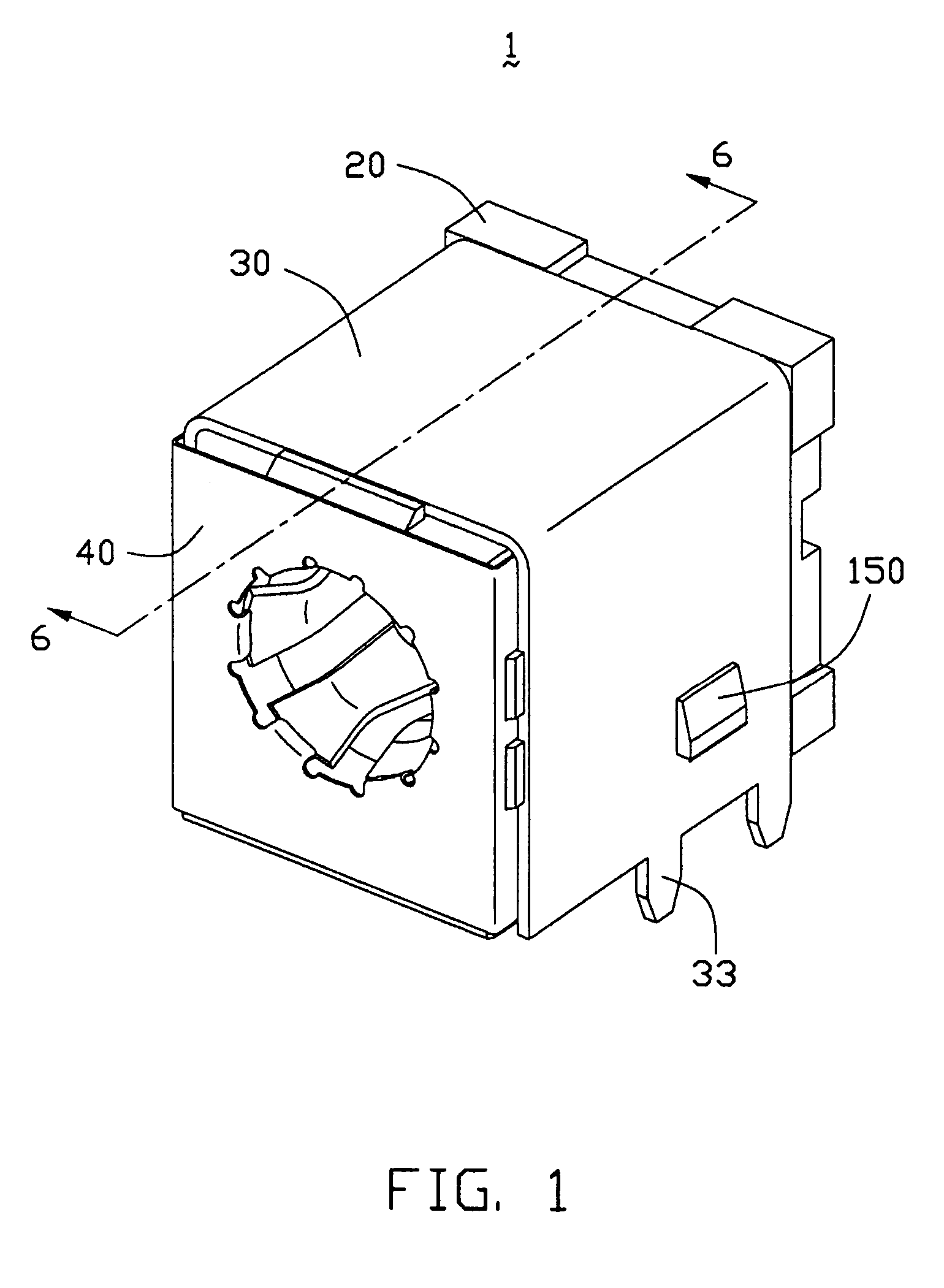
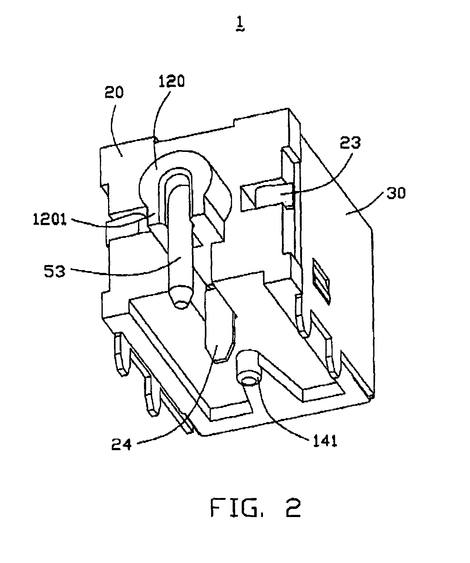
[0019]Referring to FIGS. 1 to 4, a power connector 1 of the present invention comprises an insulative housing 10, a first contact 20, a rear shield 30, a front shield 40 and a second contact 50.

[0020]Further referring to FIG. 3, the housing 10 approximately in the shape of a cubical block has a front face 11, a rear face 12, a top face 13, a bottom face 14 and two side faces 15. A tube-like receiving chamber 16 is defined within the housing 10 extending through the front face 11 thereof. The receiving chamber 16 comprises a guiding portion 160 having an inwardly decreasing diameter and a cylindrical inner portion 161 (referring to FIG. 5). An opening 130 is defined on the center of the top face 13, downwardly communicating with the cylindrical inner portion 161 of the receiving chamber 16, functioning as radiator for dispelling the heat during the voltage transmitting.

[0021]The housing 10 has a protruding ridge 101 formed on a fringe of the top face 13 adjacent the front face 11, an...


PUM


Abstract

A power connector includes a housing (10) defining a tube-like receiving chamber (16) extending through a front face (11) thereof and a receiving hole extending through a rear face (12) thereof, a first contact (20) extending into the receiving chamber, and a second contact (50) extending into the receiving hole. The receiving hole comprises a front section (17) and a rear section (18). The front section is communicating with the receiving chamber and is larger than the rear section in diameter thereof to form a step portion therebetween. The second contact (50) is a single piece and comprises an engaging portion (51) extending in the receiving chamber, a retaining portion (52) extending from the engaging portion and engaging with the step portion for preventing the second contact from moving rearwardly, and a connecting portion (53) extending from the retaining portion and comprising a bent portion engaging with the rear face of the housing for preventing the second contact from moving forwards.

Description

BACKGROUND OF THE INVENTION[0001]1. Field of the Invention[0002]The present invention relates to a power connector.[0003]2. Description of Related Art[0004]Power connectors which have a central contact and peripheral resilient contacts are widely used in the field of electronics. The central contact and the peripheral resilient contacts respectively act as a positive pole and a negative pole of a power supply for providing voltage to electrical components connecting to the power connector. For transmitting voltage steadily, it's needed to ensure a certain pressing force between the central contact and the terminal of the complementary connector while the power connector engaging with the complementary connector. Because of the pressing force, a pushing / pulling force between the central contact and the terminal of the complementary connector arises when the complementary connector is inserted or drawn out, and the pushing / pulling force will affect the secure retention of the central ...

Claims


Application Information

Patent Timeline
Patent Type & Authority Patents(United States)
IPC IPC(8): H01R12/00H01R12/71H01R13/40H01R13/648H01R24/02
CPCH01R12/716H01R13/648
Inventor CHEN, ZHI-QIANGWANG, NING
Owner HON HAI PRECISION IND CO LTD
Why Eureka
Try Eureka