Pyrolysis machine

a pyrolysis machine and pyrolysis technology, applied in the field of pyrolysis, can solve the problems of complex equipment and relatively slow throughput rate, and achieve the effect of easy control and self-regulation and energy saving

Inactive Publication Date: 2006-09-19
NOTO VINCENT H
View PDF9 Cites 24 Cited by
  • Summary
  • Abstract
  • Description
  • Claims
  • Application Information

AI Technical Summary

Benefits of technology

[0005]The principal and secondary objects of this invention are to provide a relatively simple apparatus into which the various processes of ablative pyrolysis can be accomplished in a single and continuous operation which is easily controlled and self-regulating, at a great economy of energy.

Problems solved by technology

The prior art methods require multi-step treatment, including pre-shredding of large articles, through complex equipment at a relatively slow throughput rate.

Method used


Image

  • Pyrolysis machine
  • Pyrolysis machine
  • Pyrolysis machine

Examples


Embodiment Construction

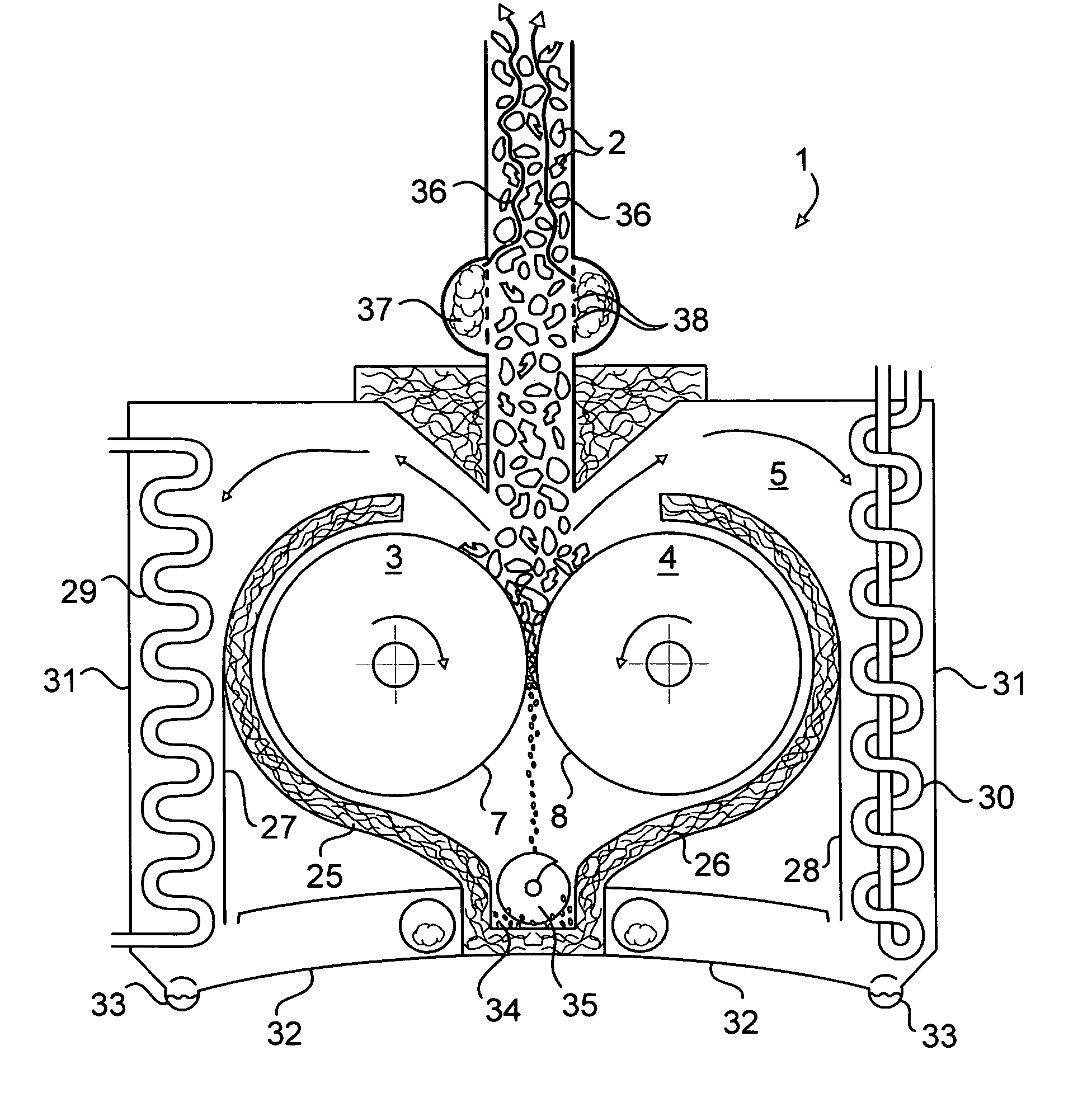
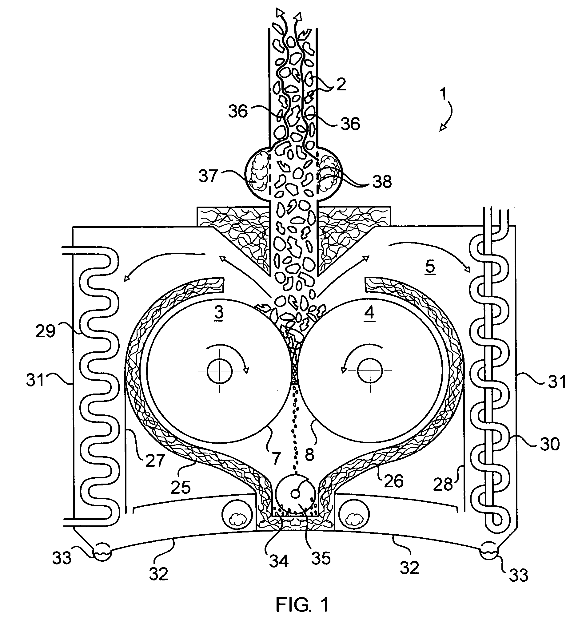
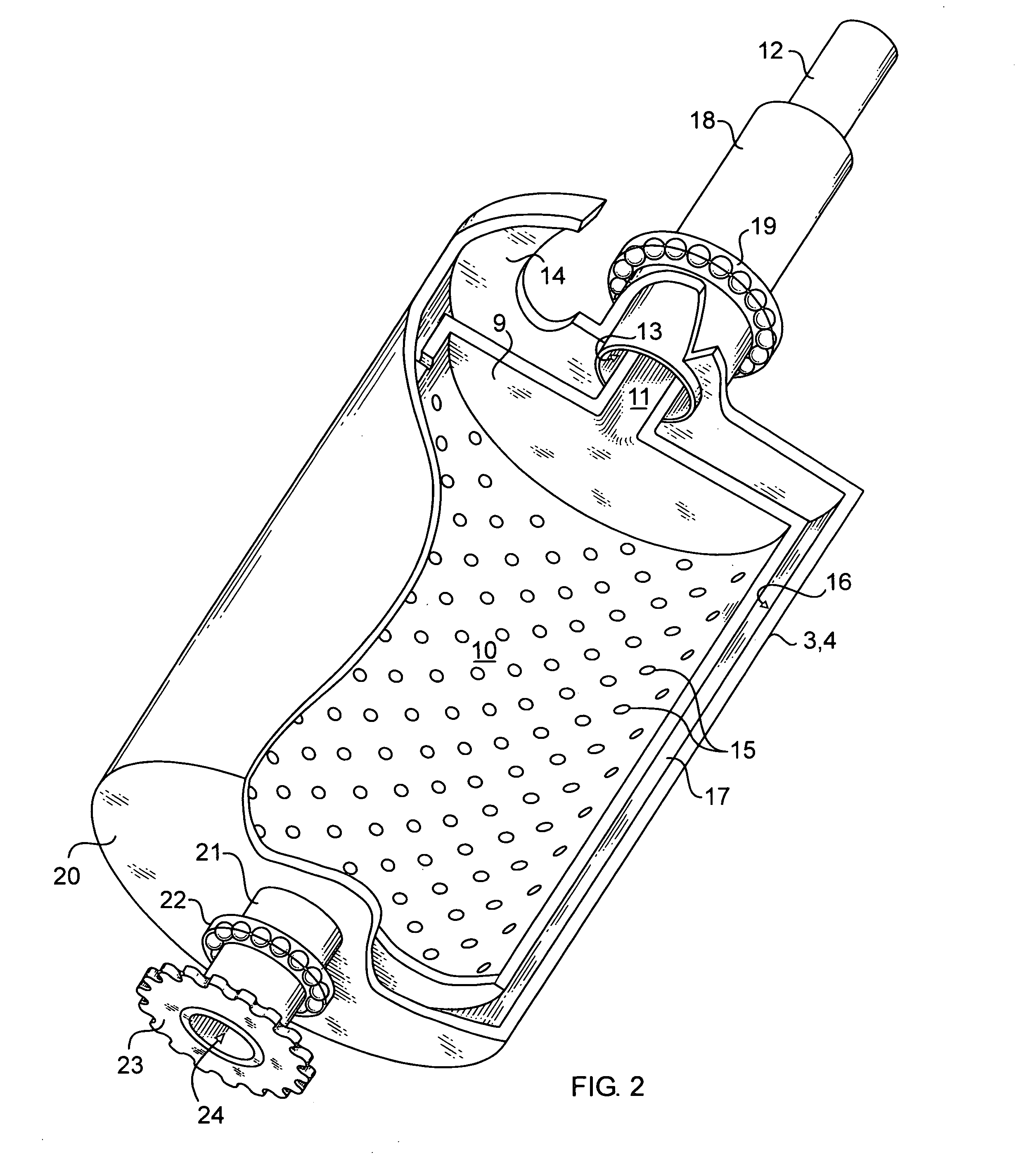
[0010]Referring now to the drawing, there is shown in the diagram of FIG. 1, an apparatus 1 particularly adapted to the practice the ablative pyrolytic process of converting biomass material such as paper, wood chips or other vegetation debris in order to extract from them useful byproducts such as oils or other liquids, and carbon particles and other solids. The biomass material 2 is fed to a pair of counter-rotating crunching rollers 3, 4 held in a sealed enclosure 5. The biomass material is dropped into the enclosure through a chute 6. The rollers are axially parallel and their circumferential outer surfaces 7, 8 are narrowly spaced-apart to grab, crunch and burn the pieces of biomass material. The walls of the rollers are made of a heat-transmitting material, preferably stainless steel and are heated from the inside. The rollers can include electric heating elements, but are preferably exposed to a flow of super-heated gas or highly heated fluid.

[0011]As more specifically illust...


PUM

PropertyMeasurementUnit
temperatureaaaaaaaaaa
incinerating temperatureaaaaaaaaaa
heat-conductingaaaaaaaaaa

Abstract

Useful byproducts are recovered through the pyrolytic processing of biomass material such as vegetation, paper, or worn tires. The process is conducted in a sealed enclosure under vacuum or other controlled atmosphere. The biomass material is ablated and burned by crunching between counter-rotating rollers whose inner walls have been exposed to a highly heated fluid. The biomass material is preheated by injecting into the feeding duct super-heated: dry steam. A condenser within the enclosure reduces resulting vapors into oils that can be drained from the enclosure pan. Solid combustion residue is abstracted from the enclosure by an Archimedes screw.

Description

FIELD OF THE INVENTION[0001]This invention relates to pyrolysis, and more particularly to method for pyrolytically processing waste biomass material into useful byproducts.BACKGROUND OF THE INVENTION[0002]The use of pyrolysis as a means of recovering oil and carbon byproducts by combustion of waste material under vacuum is well-known. An application of this process is described in “The Vacuum Pyrolysis of Used Tires and-Uses for Oil and Carbon Black Products by C. Roy, A. Chaala, and H. Darmstadt—Elsevier Journal of Analytical and Applied Pyrolysis Vol. 51 (1999) p. 201–221” which paper is incorporated into this specification by this reference.[0003]The conventional pyrolytic process involves shedding biomass material into small chips or debris that are then pyrolized under a controlled atmosphere. A common method consists of spreading the debris over a conveyer belt that passes through a high temperature furnace. Debris may also be incinerated by mixing them with super-heated sand....

Claims


Application Information

Patent Timeline
Patent Type & Authority Patents(United States)
IPC IPC(8): C10B9/00
CPCC10B47/32C10B53/02C10B53/07Y10S588/90Y02E50/14Y02P20/145Y02P20/143Y02E50/10
Inventor NOTO, VINCENT H.
Owner NOTO VINCENT H
Why Eureka
Try Eureka