Q-factor switching method and apparatus for detecting nuclear quadrupole and nuclear magnetic resonance signals
a switching method and nuclear magnetic resonance technology, applied in the field of q-factor switching method and apparatus for detecting nuclear quadrupole and nuclear magnetic resonance signals, can solve the problems of ringing, reducing detection sensitivity, and losing part of the useful signal energy of any responsive nqr (or nmr) signal, so as to reduce the bandwidth of said rf pulse, dampen transient signals, and mitigate power expended
- Summary
- Abstract
- Description
- Claims
- Application Information
AI Technical Summary
Benefits of technology
Problems solved by technology
Method used
Image
Examples
first embodiment
[0109]the best mode of the invention is directed towards an apparatus of the type I arrangement that provides a three-step change to the total Q-factor of a probe.
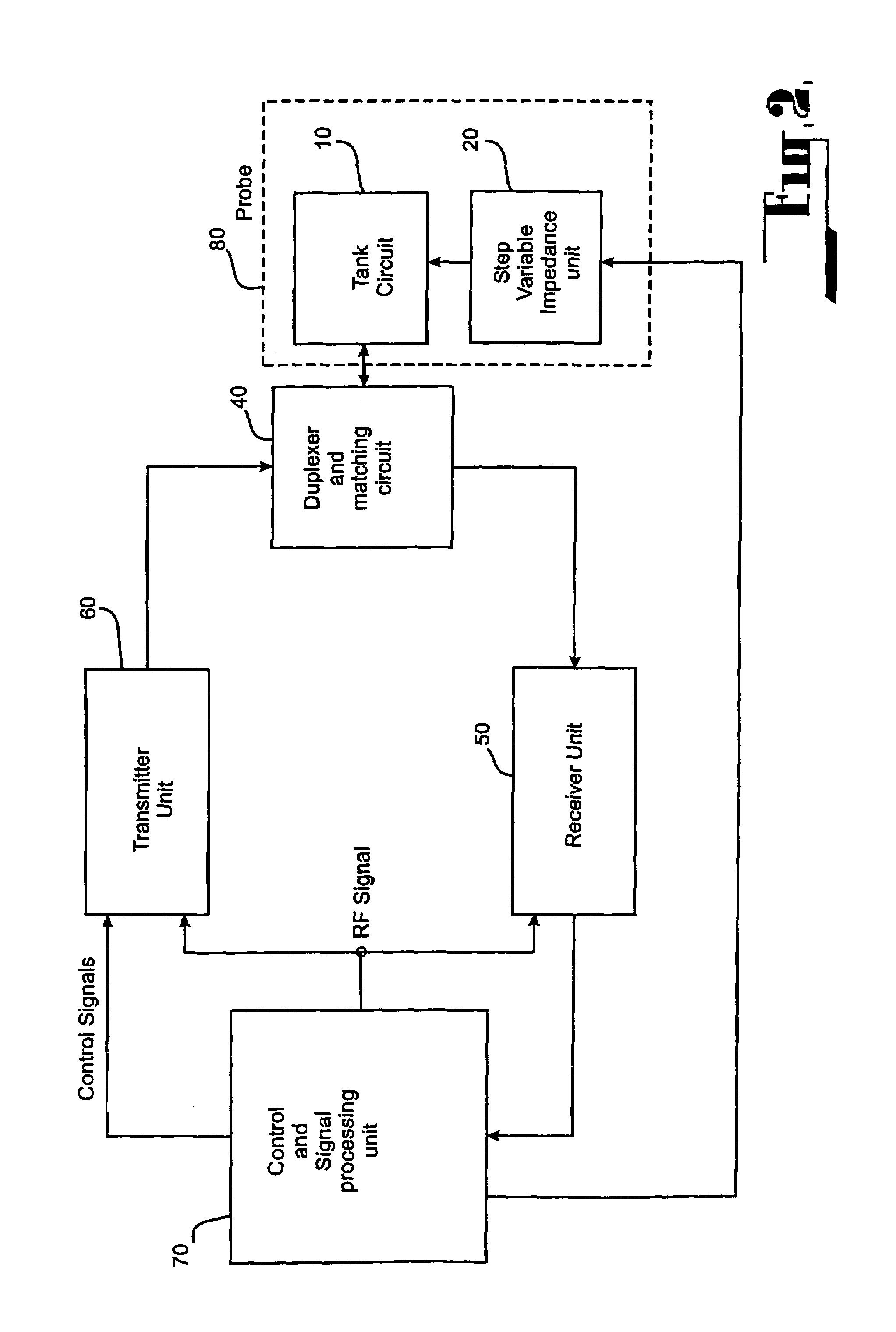
[0110]As shown in FIG. 4 the probe 80, includes a tank circuit 10 and variable step impedance unit 20. The tank circuit and the variable step impedance unit are configured to provide a Q-factor setting means for setting the Q-factor of the probe from minimal orders of magnitude to high orders of magnitude, and a Q-factor changing means having low reactance for actively changing the Q-factor of the probe without injecting a parasitic charge therein.
[0111]The Q-factor changing means actually comprises the variable impedance unit that combines with the probe to form the tank resonant circuit. The tank circuit is capable of receiving powerful RF pulses applied to the probe to excite an RF magnetic field in the probe during transmitting periods. The value of the total Q-factor of the probe is determined by the impedance of the ...
second embodiment
[0119]The second embodiment is shown in FIG. 5 and illustrates a first variant of the probe 80 that includes a tank circuit 10 and a variable step impedance unit 20. The specific feature of this particular variant of the probe 80 is that the tank circuit 10 includes a balanced high Q coil 2, which contains two similar coils 3 and 4, where the sample specimen to be investigated is placed. The tank circuit 10 also includes a variable capacitance 1 for tuning to the resonance frequency of the chosen substance to be detected. The variable step impedance unit 20, contains an inductive element 21, which is a coil wound on core 23 and which is divided into two identical coils 27 and 28, and is connected to the tank circuit 10. Depending on the frequency, the core 23 can be made either of iron-powder or ferrite materials.
[0120]For changing the impedance of variable step impedance unit 20 in discrete steps, the core 23 has four secondary control coils 29, 30, 31 and 32 wound thereon. It shou...
third embodiment
[0121]The third embodiment is directed towards an apparatus of the type II arrangement that provides a three-step change to the Q-factor of a probe to achieve the best mode of the invention.
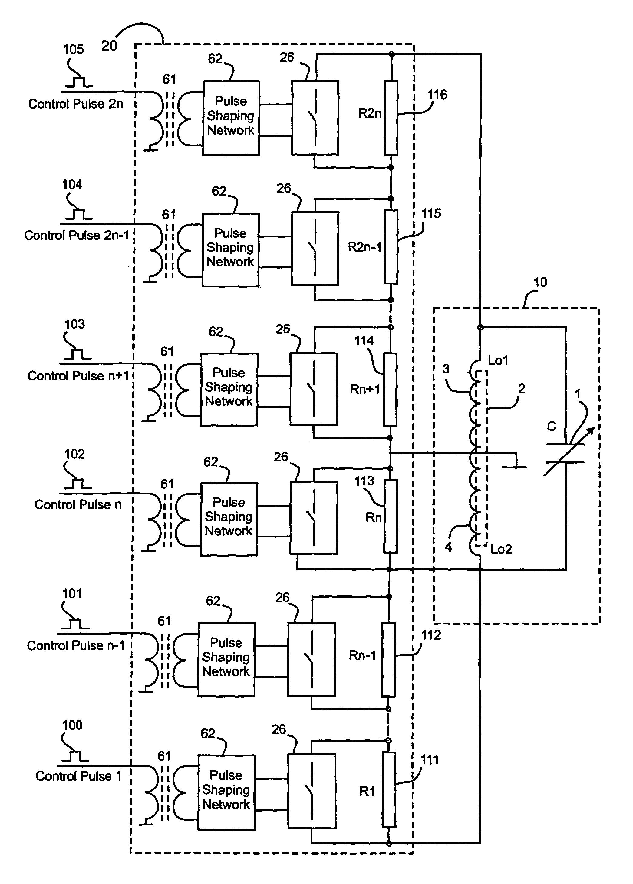
[0122]As shown in FIG. 6, the third embodiment illustrates a second variant of the probe 80, which includes a tank circuit 10 and a variable step impedance unit 20. The tank circuit 10 includes a high Q coil 2, where the sample specimen to be examined is placed and a variable capacitance 1 for tuning to the resonance frequency of the substance to be detected. The variable step impedance unit 20 in the type 11 arrangement shown contains pulse transformers 61 to isolate the drive signals, pulse shaping networks 62 to optimise the trigger input to the active switching element 26, and resistive elements (R1) 63 and (R2) 64 located in parallel with the switching elements.
[0123]The changes in the impedance of the variable step impedance unit 20 are accomplished via the control signals 92 and 93. The ef...
PUM
 Abstract
Description
Claims
Application Information
 - R&D
- Intellectual Property
- Life Sciences
- Materials
- Tech Scout
- Unparalleled Data Quality
- Higher Quality Content
- 60% Fewer Hallucinations
Browse by: Latest US Patents, China's latest patents, Technical Efficacy Thesaurus, Application Domain, Technology Topic, Popular Technical Reports.
© 2025 PatSnap. All rights reserved.Legal|Privacy policy|Modern Slavery Act Transparency Statement|Sitemap|About US| Contact US: help@patsnap.com


