Effects of flow improvement in tapered design

a technology of flow improvement and tapered design, applied in the field of musical wind instruments, can solve problems such as unsatisfactory turbulent flow, and achieve the effects of clear, rich, and high quality sound and ton

Active Publication Date: 2006-09-26
ZULI HLDG LTD
View PDF3 Cites 2 Cited by
  • Summary
  • Abstract
  • Description
  • Claims
  • Application Information

AI Technical Summary

Benefits of technology

[0005]An object of the present invention is to provide a flute-type instrument which is capable of

Problems solved by technology

This undesirable turbulent flow is created in part by the sharp change in the cross-sectional area of the flow path o

Method used


Image

  • Effects of flow improvement in tapered design
  • Effects of flow improvement in tapered design
  • Effects of flow improvement in tapered design

Examples


Embodiment Construction

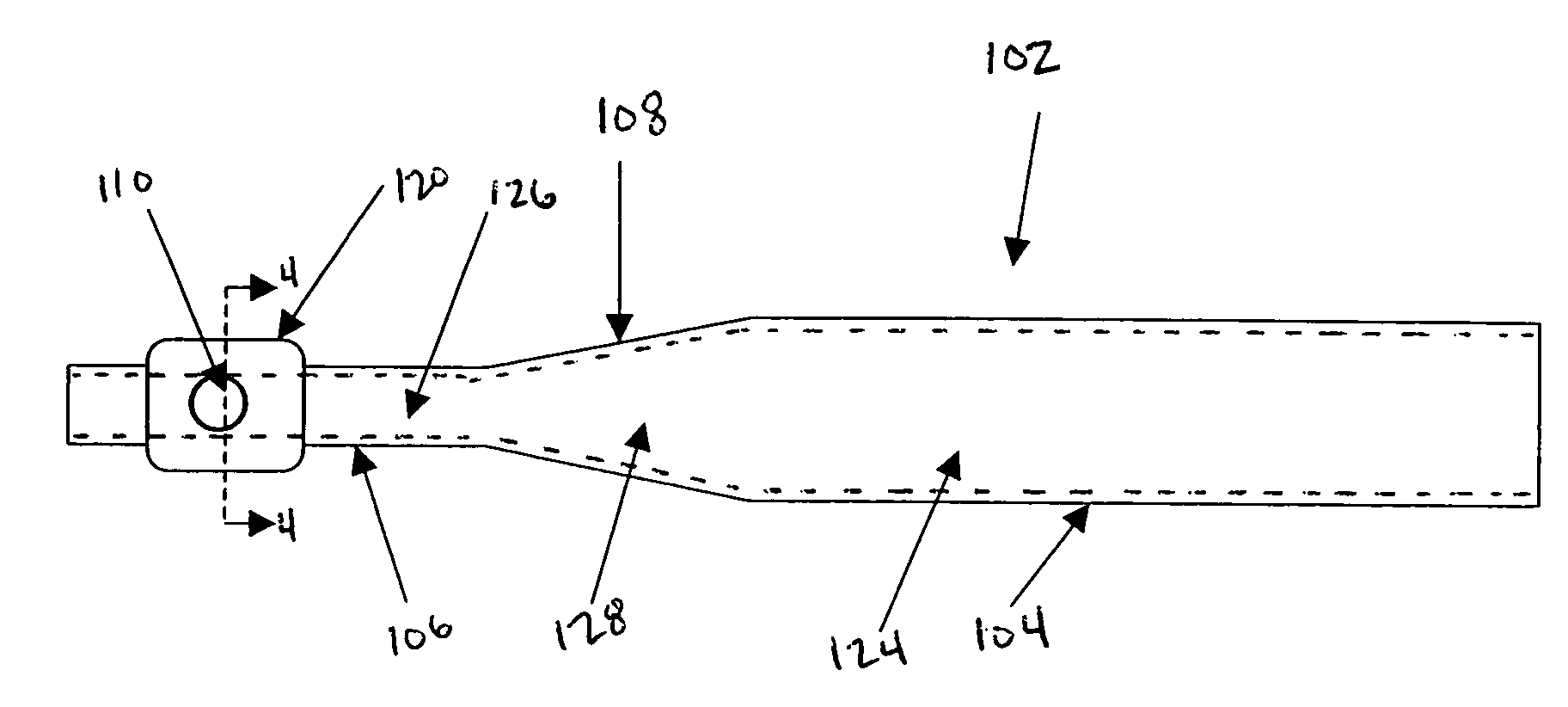
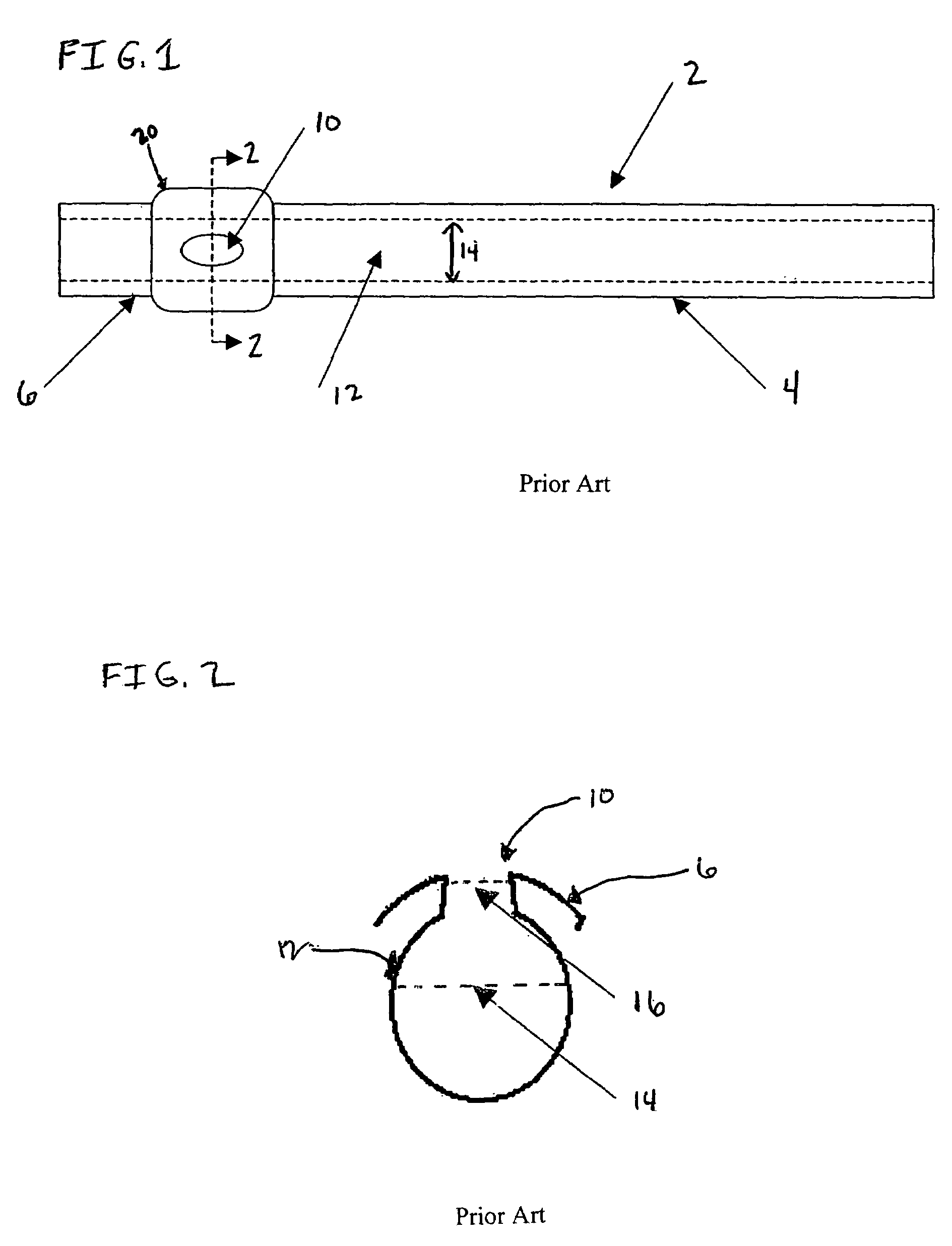
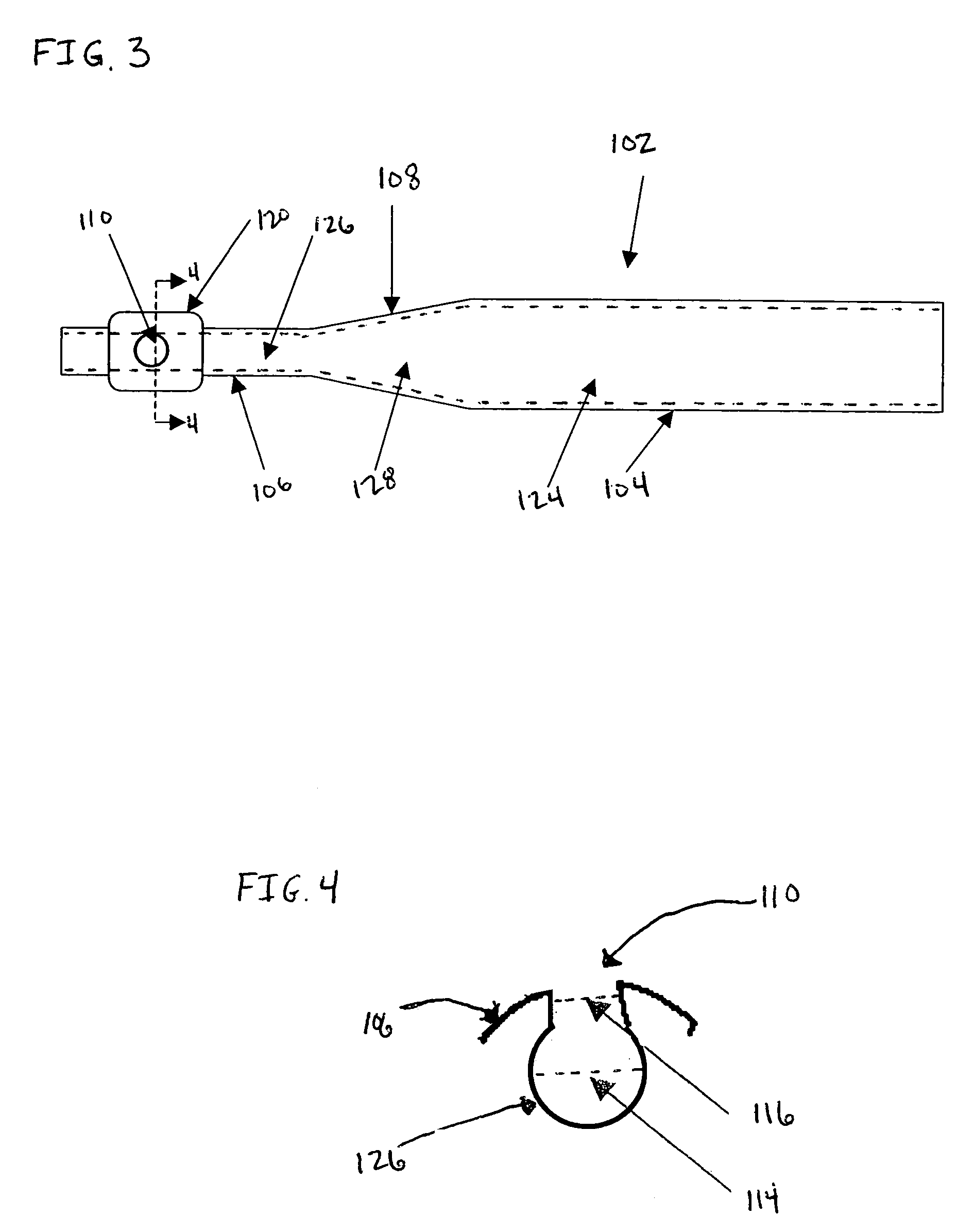
[0014]FIG. 1 illustrates a conventional flute 2 having a main section 4 and a head section 6. The head section includes a mouth opening 10 over which air is blown to produce a tone. The mouth opening 10 is typically oval or elliptical in shape. Standard mouth openings have a circumferential diameter of about 10.2 mm and a longitudinal diameter of about 12.4 mm. Some recent flutes include slightly smaller mouth openings having a circumferential diameter of about 9.8 mm and a longitudinal diameter of about 11.8 mm. As shown in FIG. 1, the head section of the flute may include a mouthpiece 20.

[0015]Flute 2 also includes a central bore 12, which extends longitudinally through the main section 4 and head section 6. The geometry of the central bore may vary. For example, a simple flute includes a cylindrical bore having a uniform diameter 14 of about 19 mm throughout its length as shown in FIG. 1. The central bore in a Boehm or modern flute is nearly cylindrical where the main section has...


PUM


Abstract

The present invention is directed to an improved flute-type instrument having a reduced bore diameter in the head section, a conical bore in the intermediate section and a standard sized bore diameter in the main section. The reduced bore diameter in the head section is dimensioned to closely correspond to the circumferential diameter of the mouth hole opening to promote laminar-like flow of air through the mouth opening and into the head section bore.

Description

FIELD OF THE INVENTION[0001]The present invention relates to musical wind instruments, and in particular to improvements in the head section of flute-type wind instruments. As used herein, the term “flute-type” is intended to include all musical instruments of the flute family, such as flutes, alto flutes, bass flutes, piccolos, fifes and the like.BACKGROUND OF THE INVENTION[0002]Flute-type wind instruments generally consist of a cylindrical tube having a central bore extending therethrough. The cylindrical tube includes a head section having a side hole mouth opening over which air is blown to produce a tone, and a main body section having a series of toneholes to play a range of notes.[0003]The central bore extending through the head section and the side hole mouth opening have a critical effect on the quality of the tone produced by flute-type wind instruments. The primary source of the degradation of tone quality, commonly referred to as the “hissing sound,” is generated in the ...

Claims


Application Information

Patent Timeline
IPC IPC(8): G10D3/02B23B47/00G10D1/00G10D7/00G10D7/02
CPCG10D7/026
Inventor RICHTER, JACOB
Owner ZULI HLDG LTD
Why Eureka
Try Eureka