Computing device with dynamic ornamental appearance

a technology of ornamental appearance and computing device, which is applied in the direction of electric variable regulation, process and machine control, instruments, etc., can solve the problem of limited feedback to users

Inactive Publication Date: 2006-09-26
APPLE INC
View PDF83 Cites 139 Cited by
  • Summary
  • Abstract
  • Description
  • Claims
  • Application Information

AI Technical Summary

Benefits of technology

[0024]The invention relates, in another embodiment, to a computer system having a computer device including a computer component for performing an operation associated with the computer system, and an illuminable housing. The computer system includes an event monitor configured to track a computer event associated with the computer system. The computer system further includes a light effect manager operatively coupled to the event monitor. The light effect manager is configured to generate light control signals when the computer event is executed by the computer system. The computer system also includes a light arrangement operatively coupled to the light effect manager and disposed in the housing. The light arrangement is configured to illuminate the illuminable housing so as to dynamically change the ornamental appearance of the housing in accordance with the light control signals associated with the computer event.

Problems solved by technology

Although displays, speakers and indicators work well, they are limited to the type of feedback they give a user.

Method used


Image

  • Computing device with dynamic ornamental appearance
  • Computing device with dynamic ornamental appearance
  • Computing device with dynamic ornamental appearance

Examples


Embodiment Construction

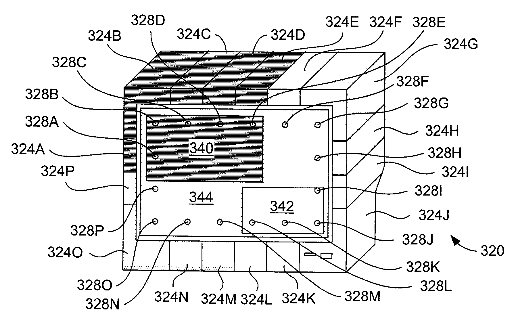
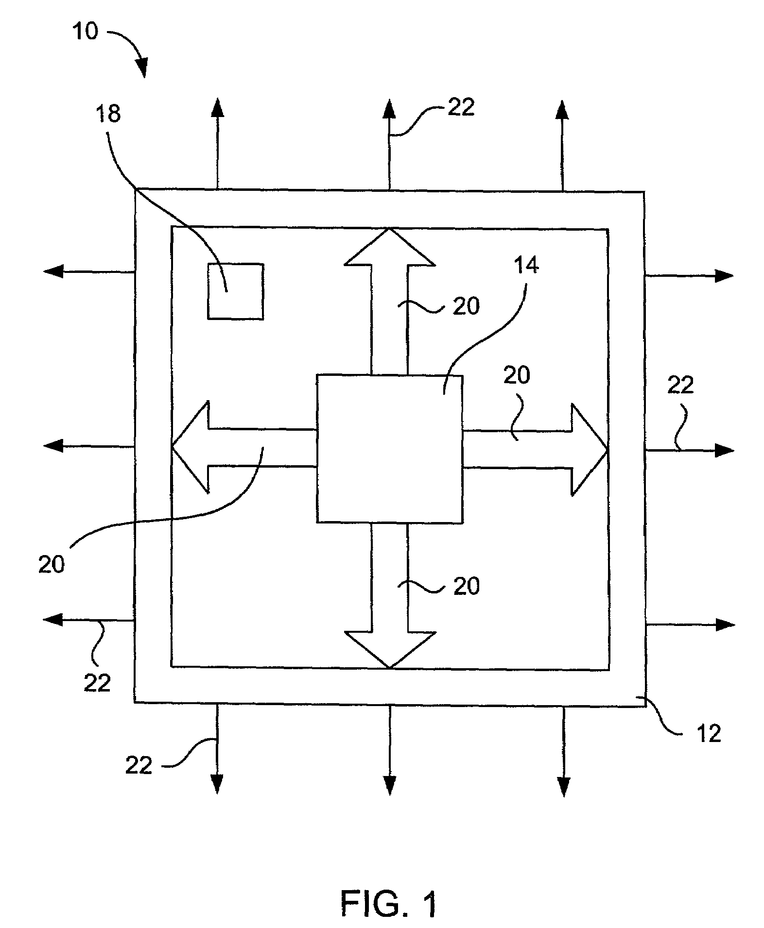
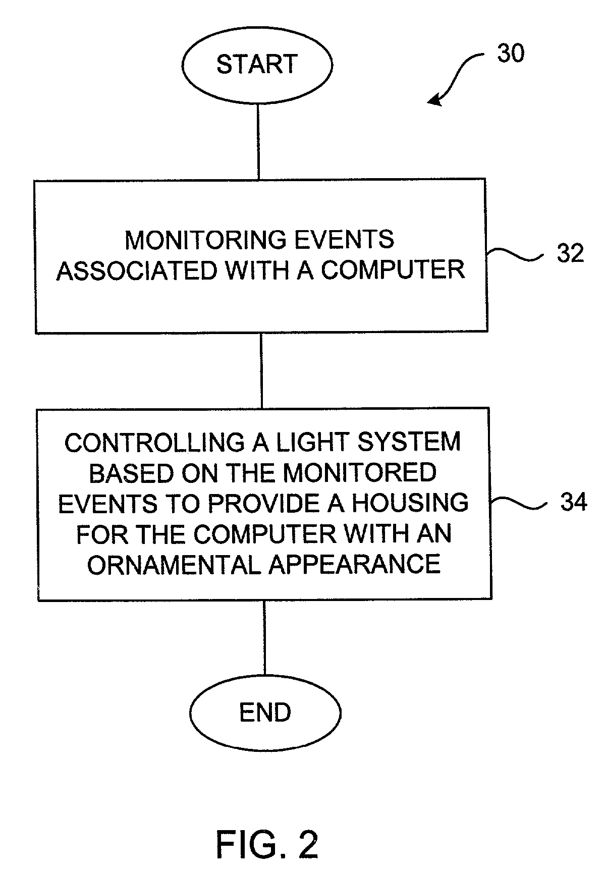
[0043]The invention pertains to electronic devices capable of dynamically changing their ornamental or decorative appearance, i.e., the outer appearance as seen by a user. The electronic devices generally include an illuminable housing. The illuminable housing, which includes at least one wall configured for the passage of light, is configured to enclose, cover and protect a light arrangement as well as functional components of the electronic device. For example, in the case of a desktop computer, the functional components may include a processor for executing instructions and carrying out operations associated with the computer, and in the case of a display monitor, the functional components may include a display for presenting text or graphics to a user. The light arrangement, which generally includes one or more light sources, is configured to produce light for transmission through the light passing wall (or walls) of the illuminable housing. As should be appreciated, the transmi...


PUM


Abstract

The invention pertains to electronic devices capable of dynamically changing their ornamental or decorative appearance, i.e., the outer appearance as seen by a user. The electronic devices generally include an illuminable housing. The illuminable housing, which includes at least one wall configured for the passage of light, is configured to enclose, cover and protect a light arrangement as well as functional components of the electronic device. The light arrangement, which generally includes one or more light sources, is configured to produce light for transmission through the light passing wall(s) of the illuminable housing. The transmitted light illuminates the wall(s) thus giving the wall a new appearance. That is, the transmitted light effectively alters the ornamental or decorative appearance of the electronic device. In most cases, the light is controlled so as to produce a light effect having specific characteristics or attributes. As such, the electronic device may be configured to provide additional feedback to the user of the electronic device and to give users the ability to personalize or change the look of their electronic device on an on-going basis. That is, a housing of the electronic device is active rather than passive, i.e., the housing has the ability to adapt and change. For example, the light may be used to exhibit a housing behavior that reflects the desires or moods of the user, that reflects inputs or outputs for the electronic device, or that reacts to tasks or events associated with operation of the electronic device.

Description

CROSS REFERENCE TO RELATED APPLICATIONS[0001]This application claims the priority of the following U.S. Patent Applications, which is hereby incorporated herein by reference:[0002]Application No.: 60 / 298,364, filed on Jun. 15, 2001 and entitled “ACTIVE ENCLOSURE FOR COMPUTING DEVICE”[0003]Application No.: 60 / 315,571, filed on Aug. 28, 2001 and entitled “COMPUTING DEVICE WITH DYNAMIC ORNAMENTAL APPEARANCE”;[0004]This application is also related to the following U.S. Patent Applications, which are hereby incorporated herein by reference:[0005]application Ser. No.: 09 / 389,915, filed on Sept. 3, 1999 and entitled “DISPLAY HOUSING FOR COMPUTING DEVICE”[0006]application Ser. No.: 09 / 426,408, filed on Oct. 25, 1999 and entitled “HOUSING FOR A COMPUTING DEVICE”[0007]application No.: 10 / 075,964, filed concurrently and entitled “ACTIVE ENCLOSURE FOR COMPUTING DEVICES”.BACKGROUND OF THE INVENTION[0008]1. Field of the Invention[0009]The present invention relates generally to a computing device....

Claims


Application Information

Patent Timeline
Patent Type & Authority Patents(United States)
IPC IPC(8): G09G3/36G06F1/16G06F1/18G09G3/32
CPCG06F1/16G06F1/182G06F1/1601Y10S345/905
Inventor KERR, DUNCAN
Owner APPLE INC
Why Eureka
Try Eureka