Expanding parallel jaw device for use with an electromechanical driver device

a technology of parallel jaws and driver devices, which is applied in the direction of surgical staples, paper/cardboard containers, incision instruments, etc., can solve the problems of increased risk of contamination of surrounding tissues with bowel contents, unusable standard instruments provided, and special accommodations

Inactive Publication Date: 2006-10-03
TYCO HEALTHCARE GRP LP
View PDF378 Cites 2042 Cited by
  • Summary
  • Abstract
  • Description
  • Claims
  • Application Information

AI Technical Summary

Benefits of technology

[0028]More particularly, with respect to the linear resecting, clamping, and stapling attachment which is the specific subject of this invention, the attachment is fitted with two drive extensions, which in operation function as extensions of the flexible drive shafts of the electromechanical driver. That is, when the attachment is mated to the electromechanical driver, the drive extensions are in mechanical communication with the flexible drive shafts such that the activation of the drive shaft motors activates the drive extensions within the linear clamping, cutting and stapling attachment The first drive extension enables the parallel spreading and closing of the jaws of the device, which form a linear clamping mechanism, while the second drive extension enables a cutting and stapling mechanism. More particularly, the linear clamping mechanism comprises a separating jaw system whereby an upper jaw is raised to permit the bowel tissue to be placed therebe

Problems solved by technology

If the cancerous tissue is too far up or down the gastrointestinal tract, then the standard instrumentation provided is unusable, thus requiring special accommodations.
These accommodations generally increase the risk of contamination of the surrounding tissues with bowel contents, increase the length of the surgery and the corresponding need for anesthesia, and eliminate the benefits of precise anastomosing and stapling which comes from utilizing a mechanized device.
As with many such devices of the prior art, all of these devices are co

Method used


Image

  • Expanding parallel jaw device for use with an electromechanical driver device
  • Expanding parallel jaw device for use with an electromechanical driver device
  • Expanding parallel jaw device for use with an electromechanical driver device

Examples


Embodiment Construction

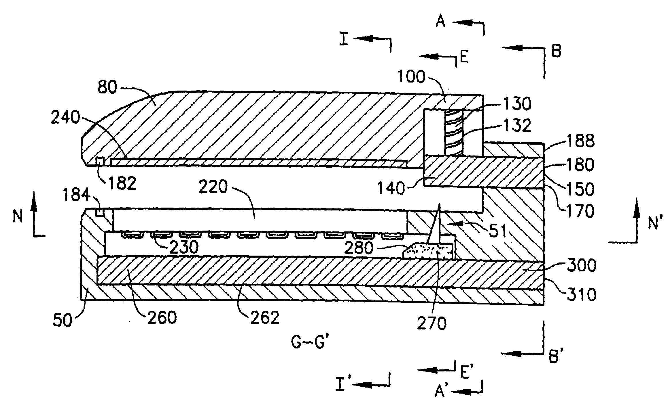
[0039]A preferred embodiment of the resecting and stapling attachment having expanding jaws which remain parallel according to the present invention, is illustrated in FIGS. 3–20. More particularly, referring now to FIGS. 3, 4 and 15, a linear clamping mechanism and a stapling and cutting mechanism according to the present invention are shown as part of a linear clamping, cutting and stapling attachment 20. Referring now also to FIGS. 5 and 6, in this preferred embodiment, the linear clamping mechanism comprises a parallel separating jaw system comprising a lower jaw 50 and an upper jaw 80 having a proximal end 100. Referring now also to FIGS. 9, 13, 16 and 19, the proximal end 100 of the upper jaw 80 has a pair of threaded vertical bores 90, through which extend a corresponding pair of vertical shafts 130. Inner threads 92 of the vertical bores 90 match outer threads 132 of the vertical shafts 130. Referring now also to FIGS. 8 and 12, the vertical shafts 130 engage a threaded uppe...


PUM


Abstract

A cutting and stapling device for use as an attachment to an electromechanical device driver comprises an upper jaw and a lower jaw which separate and close against one another in a continuously parallel alignment. The upper jaw includes a series of staple guides corresponding to one or more staples in a removable staple tray disposed within a lower jaw, whereby a blade and wedge having a threaded bore travel upon a matching threaded shaft in a channel disposed in the lower jaw below the staple tray, such that rotation of the threaded shaft causes movement of the wedge through the channel while a sloped surface of the wedge contacts the staples to push the staples against the staples guides, closing the staples.

Description

CROSS-REFERENCE TO RELATED APPLICATIONS[0001]This application is a division of U.S. application Ser. No. 10 / 341,234, filed on Jan. 13, 2003, which is now U.S. Pat. No. 6,698,643, which is a continuation of U.S. application Ser. No. 09 / 873,682, filed on Jun. 4, 2001, now U.S. Pat. No. 6,505,768, which is a continuation of U.S. application Ser. No. 09 / 351,534, which was filed on Jul. 12, 1999, now U.S. Pat. No. 6,264,087, each of which is expressly incorporated herein in its entirety by reference thereto.BACKGROUND OF THE INVENTION[0002]1. Field of the Invention[0003]The present invention relates generally to an attachment for an electromechanical device for use with anastomosing, stapling, and resecting surgical tools, and more specifically to a stapling and resecting device which can be attached to and serve as an extension of an electromechanical device driver, and most specifically to the expanding parallel jaws and the mechanisms thereof.[0004]2. Description of the Prior Art[0005...

Claims


Application Information

Patent Timeline
IPC IPC(8): A61B17/068A61B17/3211A61B17/00A61B17/072A61B17/11A61B17/115A61B17/32
CPCA61B17/07207A61B17/068A61B17/11A61B17/1155A61B2017/00039A61B2017/00398A61B2017/00734A61B2017/07214A61B2017/0725A61B2017/07271A61B2017/320052Y02A90/10
Inventor WHITMAN, MICHAEL P.
Owner TYCO HEALTHCARE GRP LP
Why Eureka
Try Eureka