Actuator device, liquid ejection head, and method of inspecting the same

a technology of liquid ejection head and actuator, which is applied in the direction of positive displacement liquid engine, mechanical vibration separation, machine/engine, etc., can solve the problem of increasing the deformation amount the inability to accurately identify and the increase of thickness errors, etc. problem, to achieve the effect of easy and accurate identification of the characteristics of the piezoelectric elemen

Inactive Publication Date: 2006-10-03
SEIKO EPSON CORP
View PDF9 Cites 4 Cited by
  • Summary
  • Abstract
  • Description
  • Claims
  • Application Information

AI Technical Summary

Benefits of technology

[0008]It is therefore an object of the present invention to provide an actuator device and a liquid ejection head that can easily and accurately identify the characteristics of a piezoelectric element. It is also an object of the present invention to provide a method of inspecting such an actuator device and a liquid ejection head.
[0019]In such a configuration, not only the total electrostatic capacity of the first piezoelectric layer and the second piezoelectric layer of the first piezoelectric element can be measured, but also the electrostatic capacity of either the first piezoelectric layer or the second piezoelectric layer of the second piezoelectric element. Since the electrostatic capacities of the first piezoelectric layer and the second piezoelectric layer of first piezoelectric element can be calculated based on the measurement results, the characteristics of the first piezoelectric element can be identified relatively accurately.
[0030]In such a configuration, the electrostatic capacities of the first piezoelectric layer and the second piezoelectric layer of the first piezoelectric element can be measured, even after an actuator unit of the liquid ejection head is assembled. As a result, the manufacturing efficiency is increased remarkably.

Problems solved by technology

With such an apparatus, however, high frequency ejection is difficult, and in order to resolve this problem, as is disclosed in Japanese Patent Publication No. 2-289352A (see FIG. 5, and page 6, line 9 of the lower left column through line 14 of the lower right column), a two-layer piezoelectric member is employed and the deformed amount of the piezoelectric element is increased.
However, since when piezoelectric layers are used to form a piezoelectric element, thickness errors occur and the characteristics of the layers are not uniform; and when printing is used for coating the piezoelectric layers, thickness errors, especially, tend to be increased.
As a result, the characteristics of the piezoelectric element can not be accurately identified.
Therefore, the characteristics of the piezoelectric element can not be accurately identified merely by referring to the overall electrostatic capacity of the piezoelectric layers.
These problems also apply for an actuator device that is mounted on a liquid ejection head, such as a liquid crystal ejection head or a coloring material ejection head.

Method used


Image

  • Actuator device, liquid ejection head, and method of inspecting the same
  • Actuator device, liquid ejection head, and method of inspecting the same
  • Actuator device, liquid ejection head, and method of inspecting the same

Examples


Embodiment Construction

[0053]The preferred embodiments of the present invention will now be described in detail with reference to the accompanying drawings.

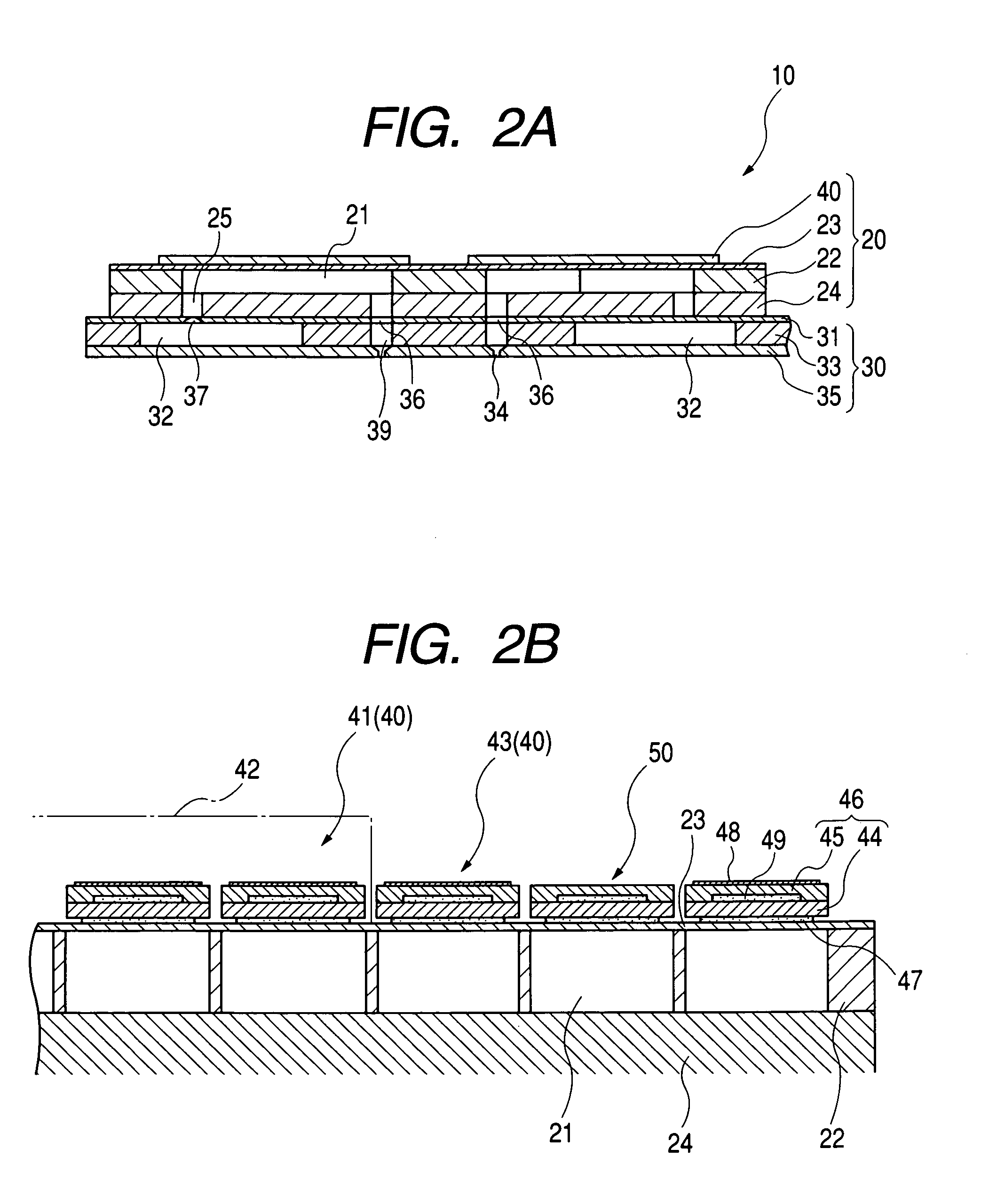
[0054]As is shown in FIGS. 1 to 3, an ink jet recording head 10 (which is one example of the liquid ejection head) according to one embodiment comprises a plurality, four in this case, of actuator units 20; and one flow path unit 30 to which the four actuator units 4 are fixed.

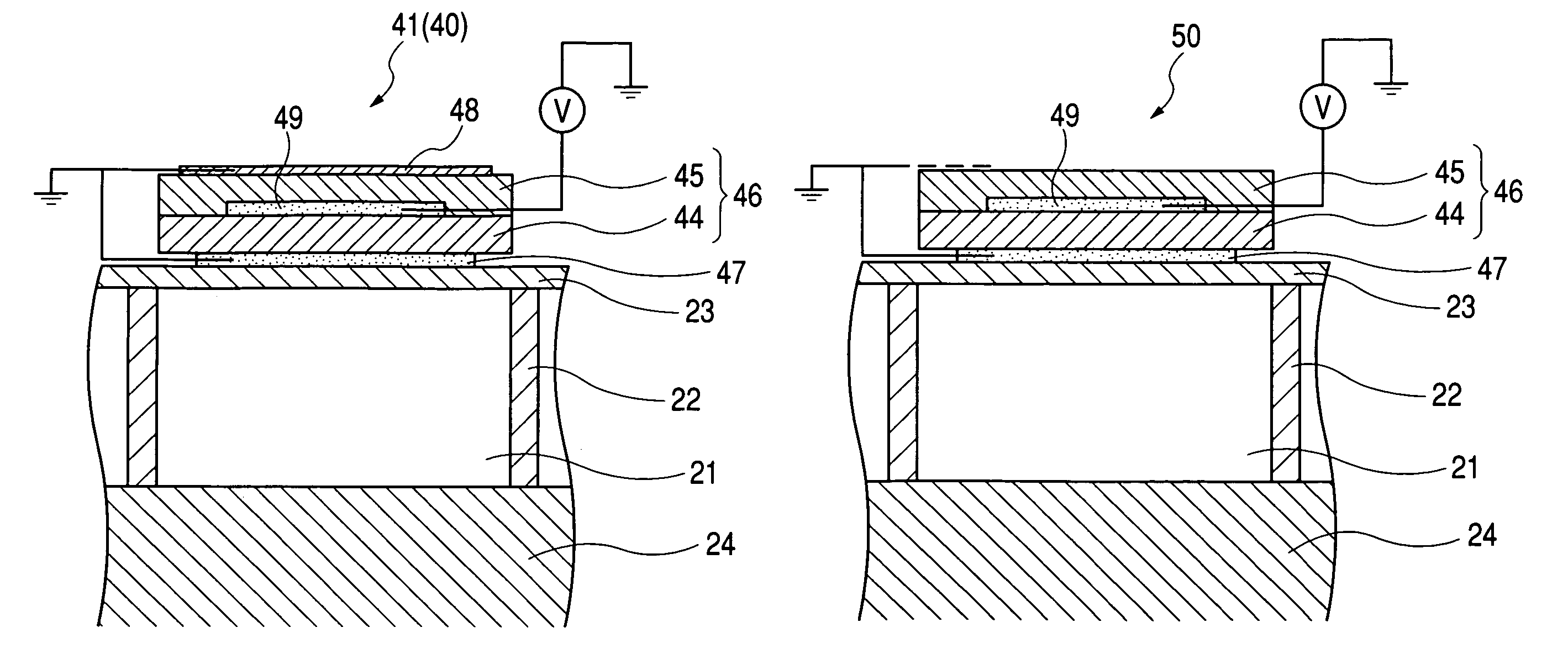
[0055]Each actuator unit 20, which serves as an actuator device, includes: piezoelectric elements 40; a flow path formation substrate 22, in which pressure generating chambers 21 are formed; a vibration plate 23, provided on one side of the flow path formation substrate 22; and a bottom plate 24, provided on the other side of the flow path formation substrate 22.

[0056]The flow path formation substrate 22 is a ceramics plate made of zirconia (ZrO2) and having a thickness of about 150 μm. In this embodiment, the pressure generating chambers 21 are arranged in two arrays in the widt...


PUM


Abstract

A substrate is formed with a pressure generating chamber. A vibration plate is joined to the substrate so as to form a part of the pressure generating chamber. A first piezoelectric element is disposed on a part of the vibration plate facing the pressure generating chamber. The first piezoelectric element includes a first electrode disposed on the part of the vibration plate, a first piezoelectric layer laminated on the first electrode, a second electrode disposed on the first piezoelectric layer, a second piezoelectric layer laminated on the first piezoelectric layer while covering the second electrode, and a third electrode disposed on the second piezoelectric layer and electrically connected to the first electrode. A second piezoelectric element is disposed on the vibration plate, and including at least the first piezoelectric layer, the second electrode, and the second piezoelectric layer, such that an electrostatic capacity of either the first piezoelectric layer or the second piezoelectric layer is adapted to be measured. The second piezoelectric element is arranged adjacent to the first piezoelectric element in a first direction corresponding to a shorter width of the first piezoelectric element.

Description

BACKGROUND OF THE INVENTION[0001]The present invention relates to an actuator device, comprising piezoelectric elements that are deformed by the application of a voltage to a piezoelectric layer. In particular, the present invention relates to a liquid ejection head wherein a part of a pressure generating chamber, which communicates with a nozzle orifice through which liquid droplets are ejected, is formed of a vibration plate, on the surface of which piezoelectric elements are disposed, so that liquid droplets are ejected when the piezoelectric elements are deformed. The present invention also relates to a method of inspecting such an actuator device and such a liquid ejection head.[0002]As one example of the liquid ejection head, there is an ink jet recording head wherein a part of a pressure generating chamber, which communicates with a nozzle orifice through which ink droplets are ejected, is formed of a vibration plate, on the surface of which an actuator device comprising piez...

Claims


Application Information

Patent Timeline
Patent Type & Authority Patents(United States)
IPC IPC(8): B41J2/045B06B1/06B41J2/055B41J2/14B41J2/16F04B43/04H01L41/09H02N2/00
CPCB41J2/14233B41J2/14274B41J2002/14491
Inventor JUNHUA, CHANG
Owner SEIKO EPSON CORP
Why Eureka
Try Eureka