Coordinate measuring apparatus and method thereof

A technology for measuring devices and measuring methods, which is applied in the direction of instruments, electrical digital data processing, and input/output processes of data processing, etc., can solve problems such as increased maintenance costs, and achieve low maintenance costs and reduced quantities.

Inactive Publication Date: 2010-07-14
ANDAMIRO
View PDF0 Cites 2 Cited by
  • Summary
  • Abstract
  • Description
  • Claims
  • Application Information

AI Technical Summary

Problems solved by technology

In addition, due to the use of a large number of luminescence sensors, its repair and maintena

Method used


Image

  • Coordinate measuring apparatus and method thereof
  • Coordinate measuring apparatus and method thereof
  • Coordinate measuring apparatus and method thereof

Examples


Embodiment Construction

[0038] The terms or vocabulary used in this specification and claims are not limited to the usual meaning or the meaning explained in the dictionary. The inventor has properly defined the concept of the term in order to explain his invention in the best way. . Therefore, relevant terms and vocabulary should be understood in accordance with the meaning and concept of the technical idea of ​​the present invention.

[0039] Hereinafter, an embodiment of the present invention will be described in detail with reference to the accompanying drawings.

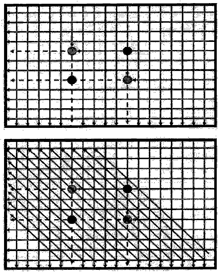
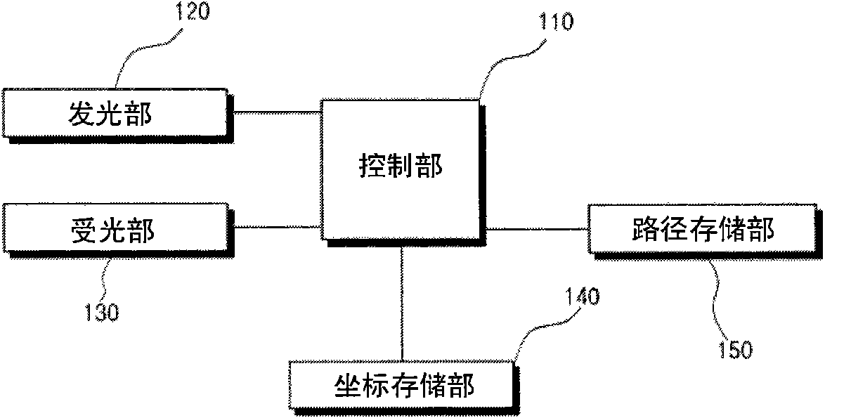
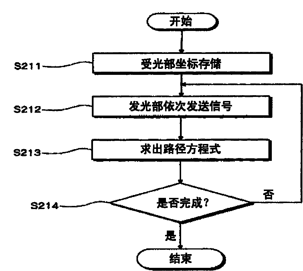
[0040] figure 2 is a block diagram representing a coordinate recognition device according to an embodiment of the present invention, image 3 is a flow chart representing an explanation of a coordinate calculation equation according to an embodiment of the present invention, Figure 4 is a flow chart illustrating a coordinate measuring method according to an embodiment of the present invention, Figure 5 to Figure 13 It is a schem...


PUM


Abstract

The invention relates to a coordinate measuring apparatus and method thereof. Specifically, the method includes: using a plurality of light receiving parts and a small quantity of light emitting parts to firstly determine the path equations of each light emitting part corresponding to each light receiving part; and then using the determined path equations to request actual coordinates of more than one targets. As few number of light emitting sensors are used, so that not only the setting fees can be reduced, but also the maintenance cost can be greatly reduced, and simultaneously the service life of the product can be prolonged.

Description

【Technical field】 [0001] The present invention relates to a coordinate recognition device and method, specifically, a coordinate measuring device and a measuring method thereof which generate actual coordinates of one or more target objects at the same time by using a small number of light emitting sensors. 【Background technique】 [0002] Generally speaking, a touch screen refers to the following screen. Without using a keyboard, you can grasp its position by touching the text or a specific position on the screen (screen) with your hand or pointer (pointer), and you can use the built-in The software performs specific processing so that input data can be obtained directly from the screen. [0003] The touch screen is to add a device called "touch panel (touch panel)" on the screen of the ordinary monitor, so as to exert the touch function. Infrared rays invisible to the naked eye are irradiated on the left, right, top, and bottom of the touch panel, forming a large number of...

Claims


Application Information

Patent Timeline
IPC IPC(8): G06F3/042
CPCG06F3/03547G06F3/0416G06F3/042
Inventor 金勇焕崔宰浩
Owner ANDAMIRO
Why Eureka
Try Eureka