Tangential dispenser and system for use within a delayed coking system

a technology of tangential dispenser and system, which is applied in the direction of separation process, fuel, evaporation, etc., can solve the problems of significant problems, process is incapable of providing even heat distribution within the vessel, and reduce the useful life of the vessel. b>2/b>

a technology of tangential dispenser and system, which is applied in the direction of separation process, fuel, evaporation, etc., can solve the problems of significant problems, process is incapable of providing even heat distribution within the vessel, and reduce the useful life of the vessel. b>2/b>

US7115190B2Active Publication Date: 2006-10-03DELTAVALVE

Image

  • Tangential dispenser and system for use within a delayed coking system
  • Tangential dispenser and system for use within a delayed coking system
  • Tangential dispenser and system for use within a delayed coking system

Examples


Embodiment Construction

[0022]It will be readily understood that the components of the present invention, as generally described and illustrated in the figures herein, could be arranged and designed in a wide variety of different configurations. Thus, the following more detailed description of the embodiments of the system and method of the present invention, and represented in FIGS. 1 through 4, is not intended to limit the scope of the invention, as claimed, but is merely representative of the presently preferred embodiments of the invention.

[0023]The presently preferred embodiments of the invention will be best understood by reference to the drawings wherein like parts are designated by like numerals throughout.

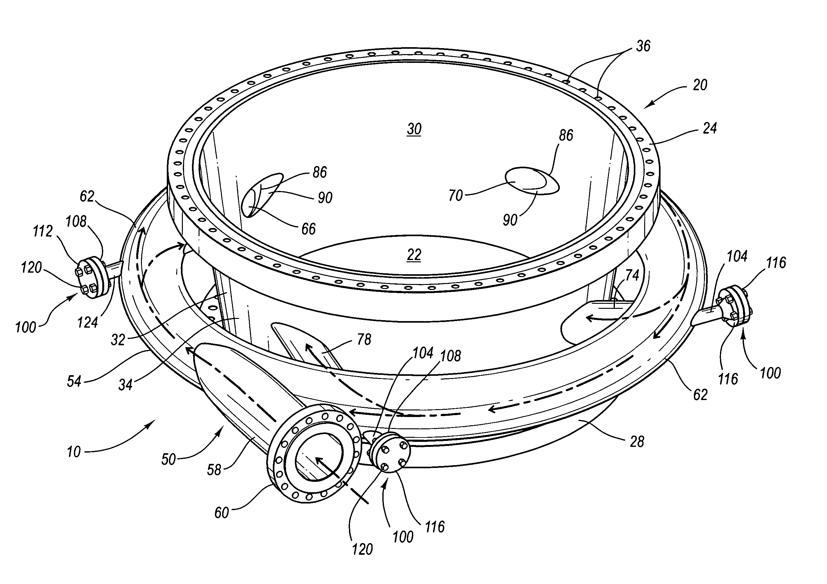
[0024]The present invention describes a method and system for improving the dispensing of residual byproducts into a container, and particularly the dispensing of petroleum byproducts into a coke drum as part of a delayed coking process, thus improving the safety, reliability, economy, ease of op...


PUM

PropertyMeasurementUnit
angleaaaaaaaaaa
angleaaaaaaaaaa
angleaaaaaaaaaa

Abstract

The present invention features a tangential injection system for use within a delayed coking system, or any other similar system. The tangential injection system comprises a spool, a tangential dispenser, and a hydro blasting system, wherein the tangential dispenser comprises a delivery main surrounding the perimeter of the spool and that functions to deliver a residual byproduct or other material to a plurality of feed lines positioned at a position or at distances around the delivery main for the purpose of providing tangential dispensing of the residual byproduct into the vessel, thus effectuating or inducing even thermal distribution throughout the vessel.

Description

RELATED APPLICATIONS[0001]This application claims priority to U.S. Provisional Application Ser. No. 60 / 448,936, filed Feb. 21, 2003, and entitled, “Tangential Dispenser System for Use Within a Delayed Coking System.”BACKGROUND[0002]1. Field of the Invention[0003]The present invention relates to a system and device for injecting or disbursing a residual by-product into a vessel, such as the several types of petroleum feed stocks into a coke drum. In particular, the present invention relates to a system and device, namely a tangential dispenser adaptable for use within a delayed coking system, wherein the tangential dispenser functions to provide a more efficient, safe, and durable way to inject and / or deposit the manufactured residual petroleum byproduct into a vessel, and particularly a coke drum vessel.[0004]2. Background of the Invention and Related Art[0005]In the hydrocarbon processing industry, many refineries recover valuable products from the heavy residual oil that remains a...

Claims


Application Information

Patent Timeline
03 Oct 2006
Publication
US7115190B2
IPC
C10B51/00; B01D3/00; B01D17/00; C10B55/00
CPC
B01D17/00; C10B1/04; C10B55/00; B01D17/0214; B01D17/0217
Inventors
LAH, RUBEN F.