Vehicle detector system with synchronized operation

a vehicle detector and synchronized technology, applied in the field of vehicle detectors, can solve problems such as exacerbate the problem of cross-talk among the loops

Active Publication Date: 2006-10-03
RENO A&E
View PDF7 Cites 36 Cited by
  • Summary
  • Abstract
  • Description
  • Claims
  • Application Information

AI Technical Summary

Problems solved by technology

This exacerbates the problem of cross-talk among the loops.

Method used


Image

  • Vehicle detector system with synchronized operation
  • Vehicle detector system with synchronized operation
  • Vehicle detector system with synchronized operation

Examples


Embodiment Construction

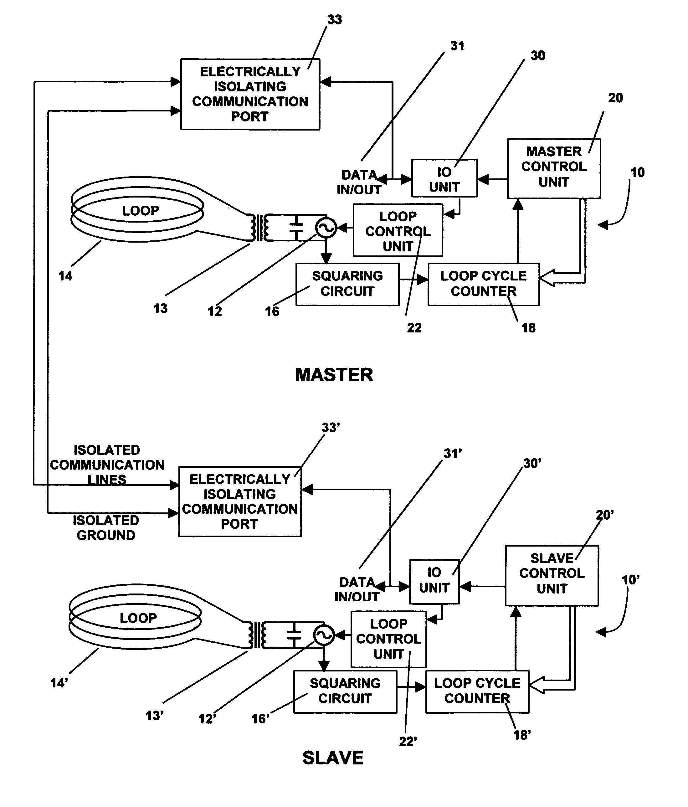
[0021]Turning now to the drawings, FIG. 1 is a block diagram of a vehicle detector system incorporating the invention. As seen in this Fig., the vehicle detector system includes a pair of vehicle detectors with synchronous intercoupling. A first vehicle detector 10 designated with the legend “MASTER” having an oscillator 12 operable over a frequency range of about 10 to about 120 kHz is coupled via a transformer 13 to an inductive loop 14. Inductive loop 14 is typically mounted within the roadbed in a position such that vehicles to be sensed will pass over the loop. Such loops are well-known and are normally found installed at controlled locations in the highway system, such as at intersections having signal heads controlled by a local intersection unit, parking lots with controlled access, railroad crossings, security barrier installations and the like. Loop 14 may also be mounted adjacent a track switch in a railway system.

[0022]The oscillator circuit 12 is coupled via a squaring ...


PUM


Abstract

A vehicle detector system having a number of individual vehicle detectors each capable of sampling a plurality of vehicle loops in mutual synchronization. One detector operates as a master detector for synchronization purposes; the other detectors are operated as slave detectors. The system can be configured for series or parallel synchronous operation. The system is particularly advantageous in installations requiring a large number of closely spaced vehicle loops each operated by a detector set to high sensitivity.

Description

BACKGROUND OF THE INVENTION[0001]This invention relates to vehicle detectors used to detect the presence or absence of a motor vehicle in an inductive loop embedded in a roadbed. More particularly, this invention relates to a vehicle detector system with synchronized operation of several vehicle detectors.[0002]Vehicle detectors have been used for a substantial period of time to generate information specifying the presence or absence of a vehicle at a particular location. Such detectors have been used at intersections, for example, to supply information used to control the operation of the traffic signal heads; have been used in railway installations for railway car detection and control; and have also been used to supply control information used in conjunction with automatic entrance and exit gates in parking lots, garages and buildings.[0003]A widely used type of vehicle detector employs the principle of period shift measurement in order to determine the presence or absence of a v...

Claims


Application Information

Patent Timeline
Patent Type & Authority Patents(United States)
IPC IPC(8): G08G1/01G08G1/042
CPCG08G1/042
Inventor LU, JASON ZHEN-YULUKE, BENJAMINJACOBS, ALLEN
Owner RENO A&E
Why Eureka
Try Eureka