False-detection resistant annular coil vehicle detector

A technology of vehicle detectors and loop coils, which is applied in the field of vehicle detectors, can solve the problems of multiple triggers, false detections, and inability to detect correctly of vehicle detectors, and achieve reduced false detections, good output waveforms, and high frequency stability Effect

Inactive Publication Date: 2010-09-15
SUN YAT SEN UNIV
View PDF0 Cites 43 Cited by
  • Summary
  • Abstract
  • Description
  • Claims
  • Application Information

AI Technical Summary

Problems solved by technology

The single threshold method of the vehicle detector will get the following three basic detection situations: correct detection; correct detection after properly adjusting the sensitivity; incorrect detection
In most cases, when a small car, a medium-sized car, or a large bus passes through the ring coil, the single threshold method can realize the normal detection of the vehicle; The wrong detection can be avoided by adjusting the sensitivity, but the sensitivity

Method used


Image

  • False-detection resistant annular coil vehicle detector
  • False-detection resistant annular coil vehicle detector
  • False-detection resistant annular coil vehicle detector

Examples


example 1

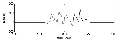
[0130] When some large vehicles pass, there may be a valley close to zero in its frequency curve. This can lead to multiple false triggers of the single threshold method. single threshold method

[0131] As shown in accompanying drawing 6, figure (a) is the frequency curve (after zeroing processing) of a big car, and the dotted line represents the threshold value reference line of single threshold value method. The frequency curve is not the actual coil data, but the superposition of two sine wave signals with different frequencies. It has a certain similarity with the coil frequency curve in actual traffic. For the convenience of describing the problem, it is used as a simulation example here. Figure (b) is the detection output of the single threshold method on the frequency curve of large vehicles. The bottom of the trough of the curve at 688ms is close to zero. It is its existence that causes the problem of multiple false triggers in Figure (b).

[0132] improved thre...

example 2

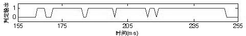
[0141] Negative peaks appearing in the cart frequency curve lead to multiple false triggers of the single threshold method.

[0142] single threshold method

[0143]Accompanying drawing 12 is the detection schematic diagram of single threshold method to the traffic situation of a large vehicle. Figure (a) is the corresponding coil frequency curve (after zeroing processing) when a large vehicle is passing, and the dotted line in the figure indicates the threshold used by the single threshold method. Same as Example 1, the frequency curve is formed by superimposing two sinusoidal signals with different frequencies. Figure (b) is the detection result of the large vehicle frequency curve in Figure (a) by the single threshold method. It can be seen that the existence of negative peaks in the cart frequency curve leads to false detection in the single threshold method.

[0144] improved threshold method

[0145] This algorithm uses a single threshold method to detect the arrival...


PUM


Abstract

The invention discloses a false-detection resistant annular coil vehicle detector comprising an oscillating circuit module, a parameter setting module, a frequency measuring module, a central processing module, an RS-232 communication module and the like. The annular coil is connected with the oscillating circuit module of a vehicle detector through a coupling transformer of 1:1 to form a high-frequency oscillating circuit; the frequency measuring module is used for carrying out shaping and frequency division on an oscillating signal and feeding the finally-calculated signal frequency valve to a singlechip control system; a singlechip is used for sampling a measuring value of the frequency measuring module at regular time; the measuring value is subjected to filter processing and is detected by an embedded vehicle detection algorithm; a detection state is displayed by an LED; and the detection result can be output by a pulse manner or transmitted to an upper computer through an RS-232 bus. The invention improves the design of a threshold detection algorithm, uses a single threshold method for detecting the arrival of the vehicle and uses a flatness determination method for detecting the leaving of the vehicle. In addition, by adopting the invention, the arrival and leaving moments of the vehicle can be accurately detected, the phenomena of false detection caused by multiple false triggers are reduced, and the stability of the system is enhanced.

Description

technical field [0001] The invention relates to a vehicle detector, in particular to an anti-false detection loop coil vehicle detector. Background technique [0002] The toroidal coil vehicle detector consists of three parts: the toroidal coil as an inductor, the transmission feeder and the detection processing unit. The toroidal coil wound by several turns of metal wire is buried under the road surface and connected with the detection and processing unit of the roadside device through the feeder. [0003] The toroidal coil, the feeder and some circuits of the detection unit form an oscillating circuit. When the oscillating circuit is powered on, an alternating electromagnetic field is formed around the toroidal coil. When the vehicle passes or stops on the road in the coil area, on the one hand, the magnetic permeability of the space around the coil will increase due to the presence of ferromagnetic materials in the vehicle body, which will increase the inductance of the ...

Claims


Application Information

Patent Timeline
IPC IPC(8): G08G1/042
Inventor 张辉黄永强陈古典
Owner SUN YAT SEN UNIV
Why Eureka
Try Eureka