Cooling water intake system

a technology of water intake system and cooling water, which is applied in the direction of water cleaning, domestic cooling apparatus, lighting and heating apparatus, etc., can solve the problems of affecting the survival rate of organisms, affecting the cooling effect of local receiving water, and causing a variety of negative environmental effects on the local receiving water

a technology of water intake system and cooling water, which is applied in the direction of water cleaning, domestic cooling apparatus, lighting and heating apparatus, etc., can solve the problems of affecting the survival rate of organisms, affecting the cooling effect of local receiving water, and causing a variety of negative environmental effects on the local receiving water

US7118307B2Inactive Publication Date: 2006-10-10SUBSTRATUM INTAKE SYST

Image

  • Cooling water intake system
  • Cooling water intake system
  • Cooling water intake system

Examples


Embodiment Construction

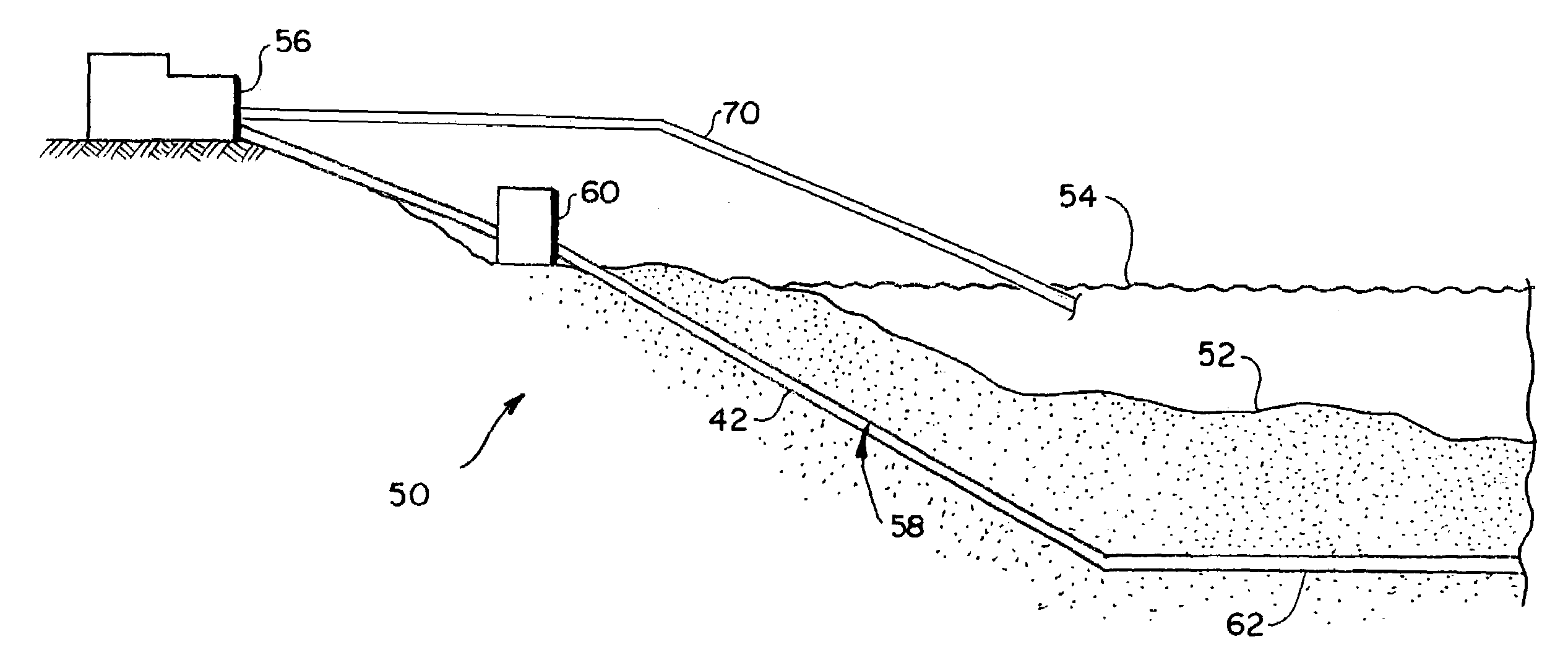
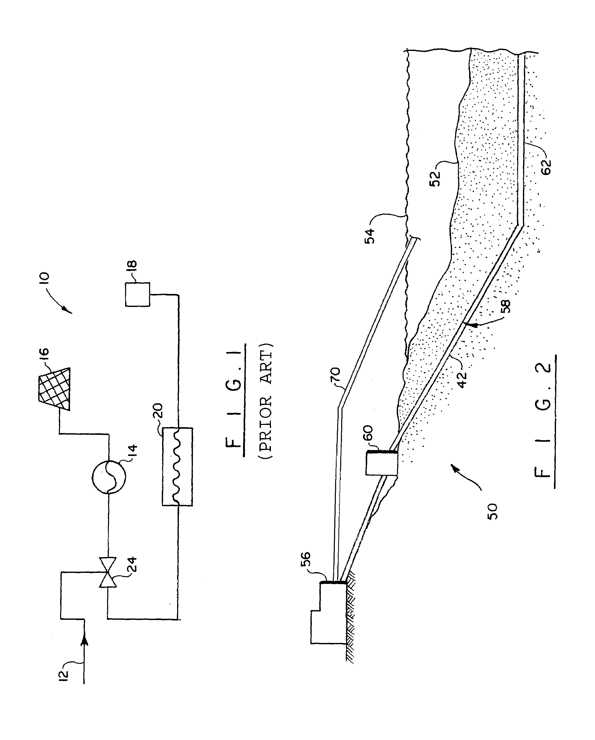
[0026]Referring to FIG. 2, a cooling water system 50 is operative to deliver influent water from under a bottom 52 of a water reservoir 54 to an industrial facility 56 to transfer heat from equipment or processes therein. Although the cooling water system 50, as discussed here, is described in association with a power plant, a variety of facilities that may benefit from using a cooling water from under the bottom 52 and including, for example, nuclear plants and desalination plants, can utilize this system. The water reservoir 54 can be any body of water including oceans, seas, lakes and rivers subject only to a predominantly sandy substrate constituting the bottom 52. It is preferable for the most desirable operation of the cooling system that the bottom 52 be mostly sandy, as opposed to clay or rock, since the sand has a well-known and unique ability to filtrate incoming water.

[0027]Conveyance of water from under the bottom 52 to the facility is realized by a water delivery assemb...


PUM


Abstract

A cooling water intake system is configured to minimize entrainment, impingement and thermal plumes associated with the operation of onshore industrial facilities, such as a power plant, and includes a delivery system guiding ground waters from under the sand bottom of the water reservoir including oceans, seas, lakes and rivers to the industrial facilities.

Description

BACKGROUND OF THE INVENTION[0001]1. Field of the Invention[0002]The invention relates to a method and system for delivering ground waters from under the bottom of water reservoirs for cooling equipment of onshore facilities.[0003]2. Discussion of the Prior Art[0004]A variety of industrial facilities generating or consuming electric energy necessarily use a cooling medium for providing proper functioning of the facilities' equipment. For example, steam power plants, typically generating electric energy, operate with a cooling medium such as a water / steam mixture, carried in an evaporator circuit of the steam power plant. The steam generated in the process expands to perform work in the steam turbine of the steam power plant and is subsequently fed to the condenser for producing a working medium. The latter is normally condensed by heat exchange with cooling water, which is fed directly to the condenser from a water reservoir, such as an ocean, sea, river or lake. This is known as an ...

Claims


Application Information

Patent Timeline
10 Oct 2006
Publication
US7118307B2
IPC
F24J3/08; E02B9/04; E03B3/14
CPC
E02B9/04; E03B3/14; F28B9/06; Y02E10/22; Y02A20/00; Y02E10/20; Y02P80/10
Inventors
STOECKER, ROY R.; HAIRR, LELAND M.