Piezoelectric step-motion actuator

a step-motion actuator and step-motion technology, applied in piezoelectric/electrostrictive/magnetostrictive devices, piezoelectric/electrostriction/magnetostriction machines, electrical apparatus, etc., can solve the problem of low energy density of step-motion actuators using these concepts, and achieve higher energy density and more useful

Active Publication Date: 2006-10-10
HONEYWELL FED MFG & TECHNOLOGI
View PDF10 Cites 27 Cited by
  • Summary
  • Abstract
  • Description
  • Claims
  • Application Information

AI Technical Summary

Benefits of technology

[0012]Thus, it will be appreciated that the step-motion actuator of the present invention provides a number of substantial advantages over the prior art, including, for example, a higher, more useful energy density not achieved in prior art step-motion actuator concepts. Furthermore, the flight actuator mechanism of the present invention is substantially more flexible and adaptable in design and therefore more universally applicable than prior art step-motion actuator concepts.

Problems solved by technology

In general, however, step-motion actuators using these concepts are in the early stages of development and still suffer from a number of problems and disadvantages.
For example, energy density in these step-motion actuators is typically too low to be useful.
Also, none of the current concepts have proven to be universally applicable.

Method used


Image

  • Piezoelectric step-motion actuator
  • Piezoelectric step-motion actuator
  • Piezoelectric step-motion actuator

Examples


first embodiment

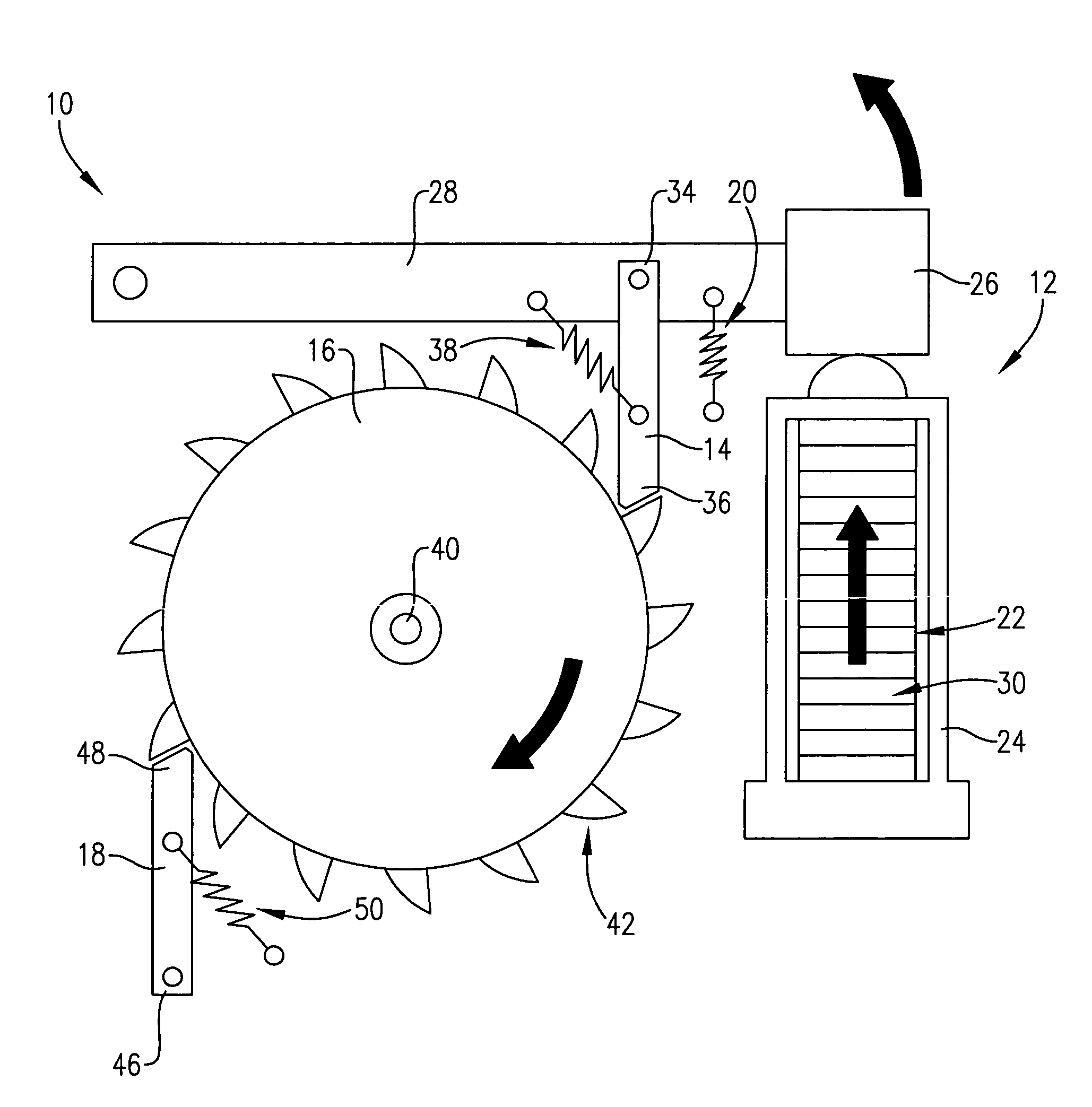
[0015]FIG. 1 is a schematic depiction of a preferred first embodiment of the piezoelectric step-motion actuator of the present invention;

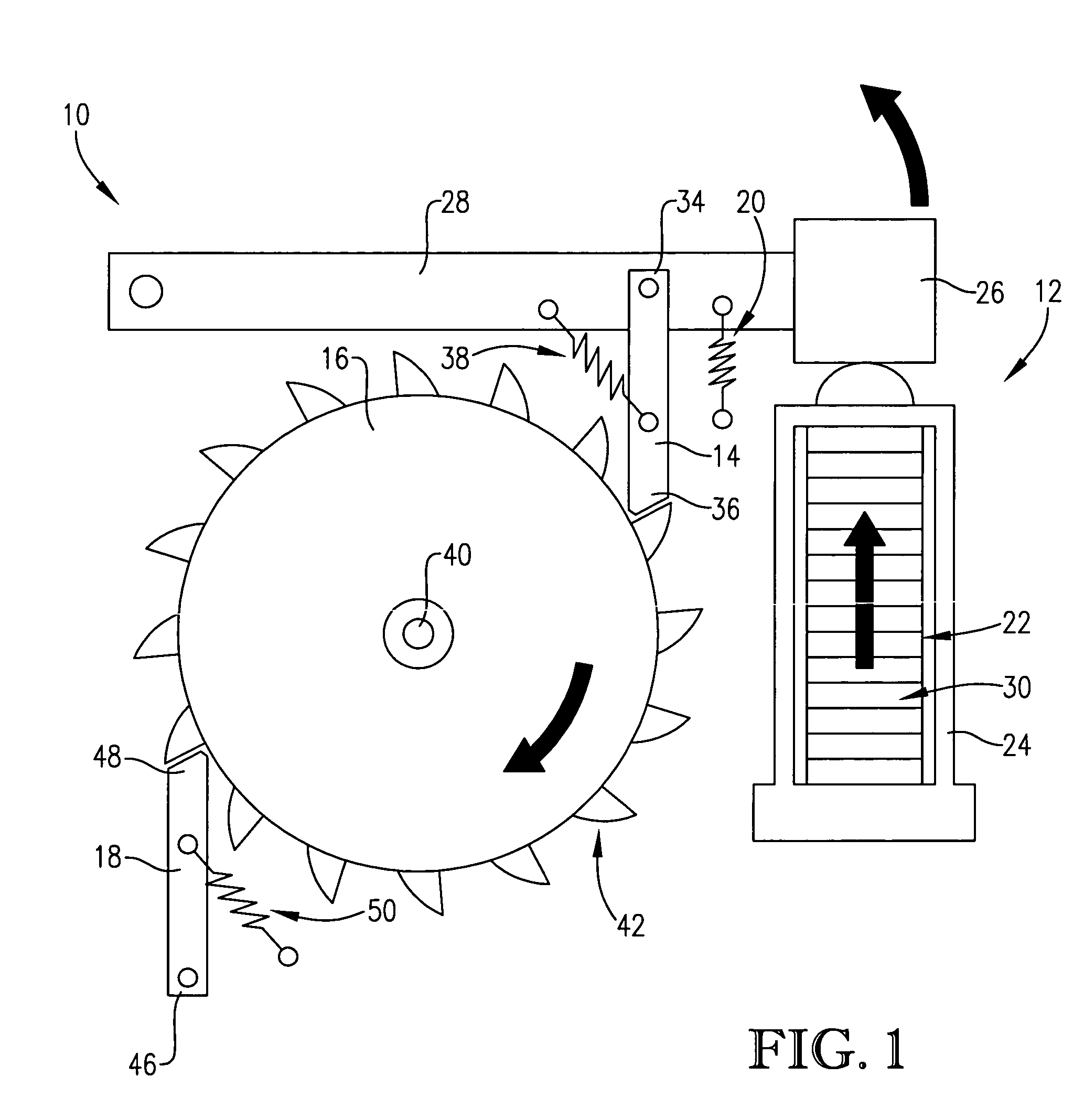
[0016]FIG. 2 is a depiction illustrating the concept and principle of operation of a flight actuator component of the step-motion actuator shown in FIG. 1, wherein the flight actuator is shown in an initial or rest position;

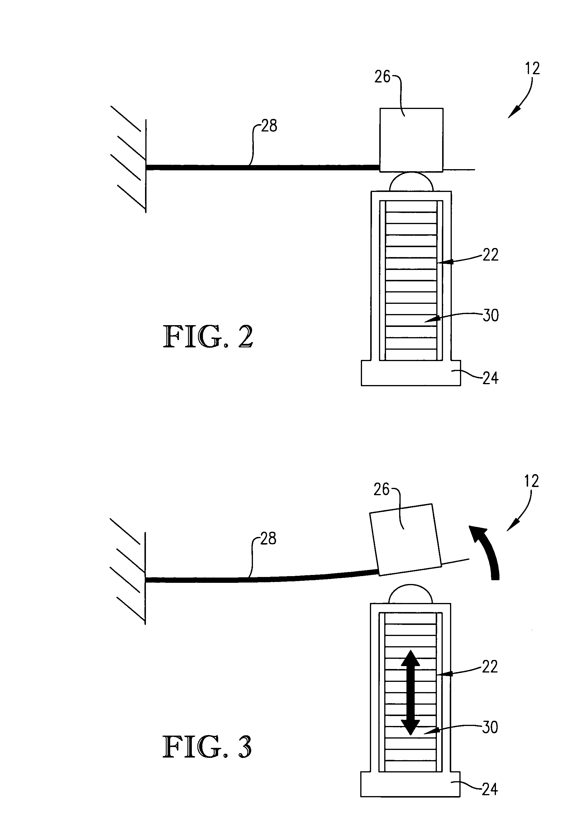
[0017]FIG. 3 is a depiction of the flight actuator component of the FIG. 2, wherein the flight actuator is shown in a launched or actuated position;

second embodiment

[0018]FIG. 4 is a schematic depiction of an alternative second embodiment of the step-motion actuator of the present invention; and

third embodiment

[0019]FIG. 5 is a schematic depiction of an alternative third embodiment of the step-motion actuator of the present invention.

DETAILED DESCRIPTION OF A PREFERRED EMBODIMENT

[0020]With reference to the figures, a step-motion actuator 10 is described, shown, and otherwise disclosed herein in accordance with a preferred embodiment of the present invention. Broadly, the step-motion actuator 10 converts electrical energy into kinetic energy through piezoelectric action, and then converts the kinetic energy into stepped motion. Possible uses and applications for the step-motion actuator 10 include, for example, driving LiGA-produced micro-sized stronglinks or other micro-mechanisms. It should be noted, however, that the step-motion actuator 10 of the present invention is not limited with regard to size or fabrication method, and may therefore be used to provide stepped rotary or linear motion on substantially any scale and for substantially any torque, speed, or step-size specifications.

[0...


PUM


Abstract

A step-motion actuator using piezoelectric material to launch a flight mass which, in turn, actuates a drive pawl to progressively engage and drive a toothed wheel or rod to accomplish stepped motion. Thus, the piezoelectric material converts electrical energy into kinetic energy of the mass, and the drive pawl and toothed wheel or rod convert the kinetic energy of the mass into the desired rotary or linear stepped motion. A compression frame may be secured about the piezoelectric element and adapted to pre-compress the piezoelectric material so as to reduce tensile loads thereon. A return spring may be used to return the mass to its resting position against the compression frame or piezoelectric material following launch. Alternative embodiment are possible, including an alternative first embodiment wherein two masses are launched in substantially different directions, and an alternative second embodiment wherein the mass is eliminated in favor of the piezoelectric material launching itself.

Description

FEDERALLY SPONSORED RESEARCH OR DEVELOPMENT PROGRAM[0001]The present invention was developed with support from the U.S. government under Contract No. DE-AC04-01 AL66850 with the U.S. Department of Energy. Accordingly, the U.S. government has certain rights in the present invention.BACKGROUND OF THE INVENTION[0002]1. Field of the Invention[0003]The present invention relates broadly to stepper motors or other step-motion actuators and mechanisms for accomplishing stepped motion. More particularly, the present invention concerns a stepper motor or other step-motion actuator that uses piezoelectric material to launch one or more flight masses, which, in turn, actuate a drive pawl to progressively engage and drive a toothed wheel or rod to accomplish stepped motion. Thus, the piezoelectric material converts electrical energy into kinetic energy of the masses, and the drive pawl and toothed wheel or rod convert the kinetic energy of the masses into the desired rotary or linear stepped mot...

Claims


Application Information

Patent Timeline
Patent Type & Authority Patents(United States)
IPC IPC(8): H01L41/08
CPCH02N2/021H02N2/101
Inventor MENTESANA, CHARLES P.
Owner HONEYWELL FED MFG & TECHNOLOGI
Why Eureka
Try Eureka