
Dynamic vehicle signaling device and system

a signaling device and vehicle technology, applied in the direction of signalling/lighting devices, vehicle components, optical signalling, etc., can solve the problems of not being able to communicate information, the lamp itself is not dynamic,

Inactive Publication Date: 2006-10-10
SUBBARAMAN RAMESH
View PDF14 Cites 31 Cited by
  • Summary
  • Abstract
  • Description
  • Claims
  • Application Information

AI Technical Summary

Benefits of technology

"The present invention is a vehicle signaling system that uses detectors to measure the movement of the steering column or other parts of the steering system. These measurements are then sent to multiple signaling lights, which emit patterns that vary based on the detected movement. The system may also include a logic control unit that converts the detectors' measurements into a specific lighting pattern. Additionally, the system may include detectors that sense changes in vehicle speed or direction. The technical effect of this invention is to provide a more intuitive and effective signaling system for vehicles, making it easier for drivers to understand and respond to the vehicle's movements."

Problems solved by technology

This is insufficient when the center of the vehicle is not easily determined by others, such as in the many circumstances of limited visibility, including nighttime and during inclement weather.
The lamps themselves are also not dynamic in that they fail to communicate any information about the magnitude of the turn, the rate of turn, the speed of the car as it enters the turn or during the turn, or the direction of the car (forward or reverse) as it initiates the turn.
There are often instances in current signaling systems therefore when the ratcheting mechanism turns off the turn signal lamps prematurely, before the turn is complete.
Likewise, there are often other instances when the mechanism does not switch off the lamp at all, such as when the turn angle is gradual or small in magnitude or when the operator mistakenly turned on the turn signal.

Method used


Image

  • Dynamic vehicle signaling device and system
  • Dynamic vehicle signaling device and system
  • Dynamic vehicle signaling device and system

Examples


Embodiment Construction

)

[0019]The detailed description set forth below in connection with the appended drawings is intended as a description of presently-preferred embodiments of the invention and is not intended to represent the only forms in which the present invention may be constructed and / or utilized. The description sets forth the functions and the sequence of steps for constructing and operating the invention in connection with the illustrated embodiments. However, it is to be understood that the same or equivalent functions and sequences may be accomplished by different embodiments that are also intended to be encompassed within the spirit and scope of the invention.

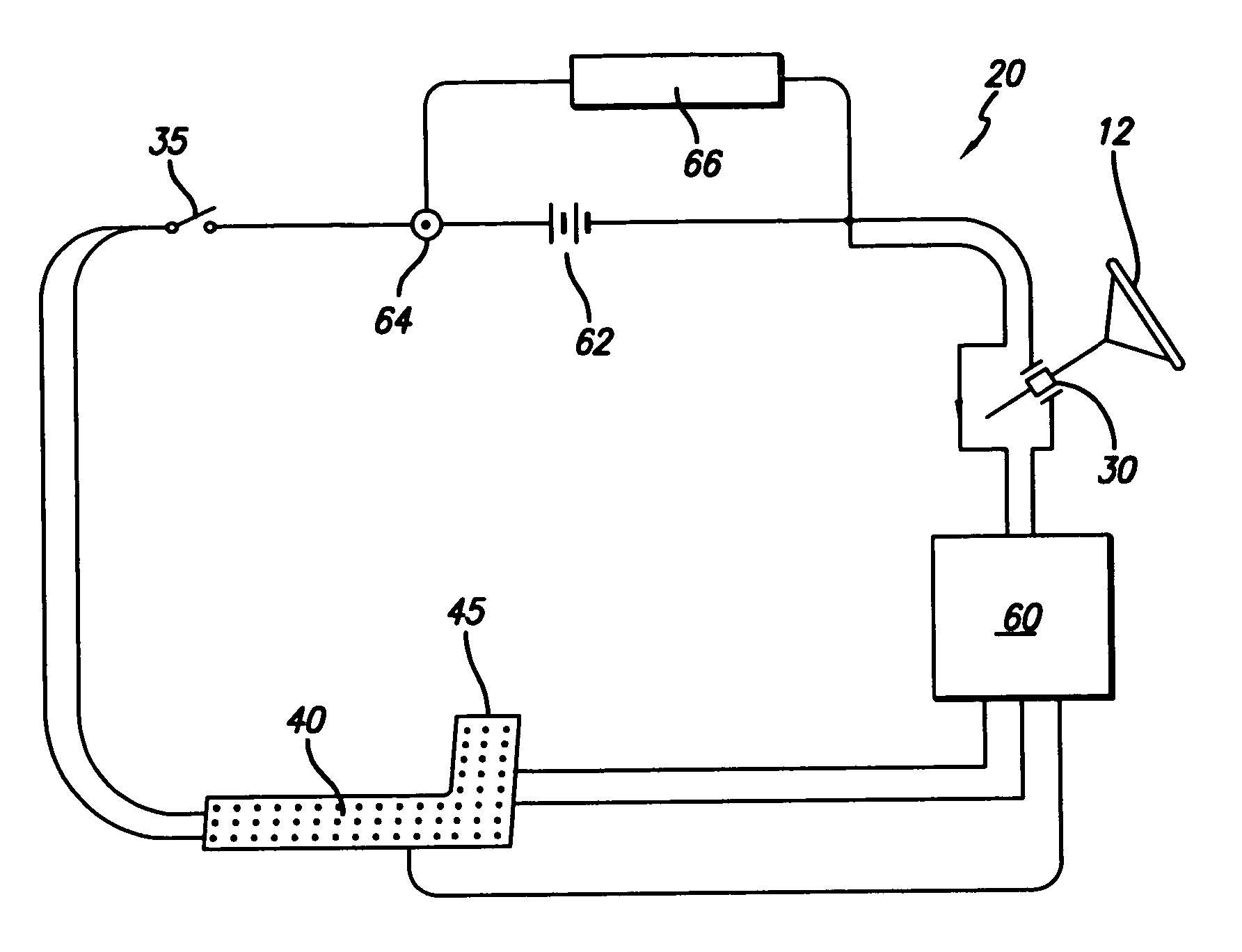
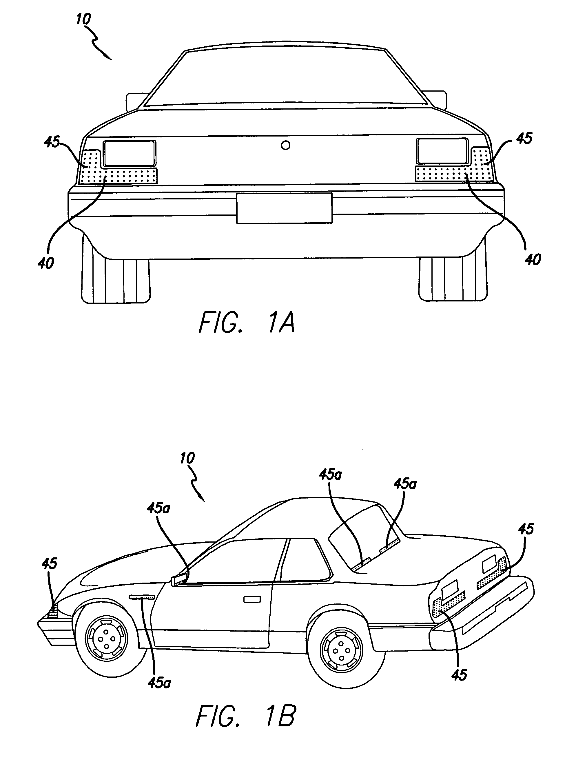
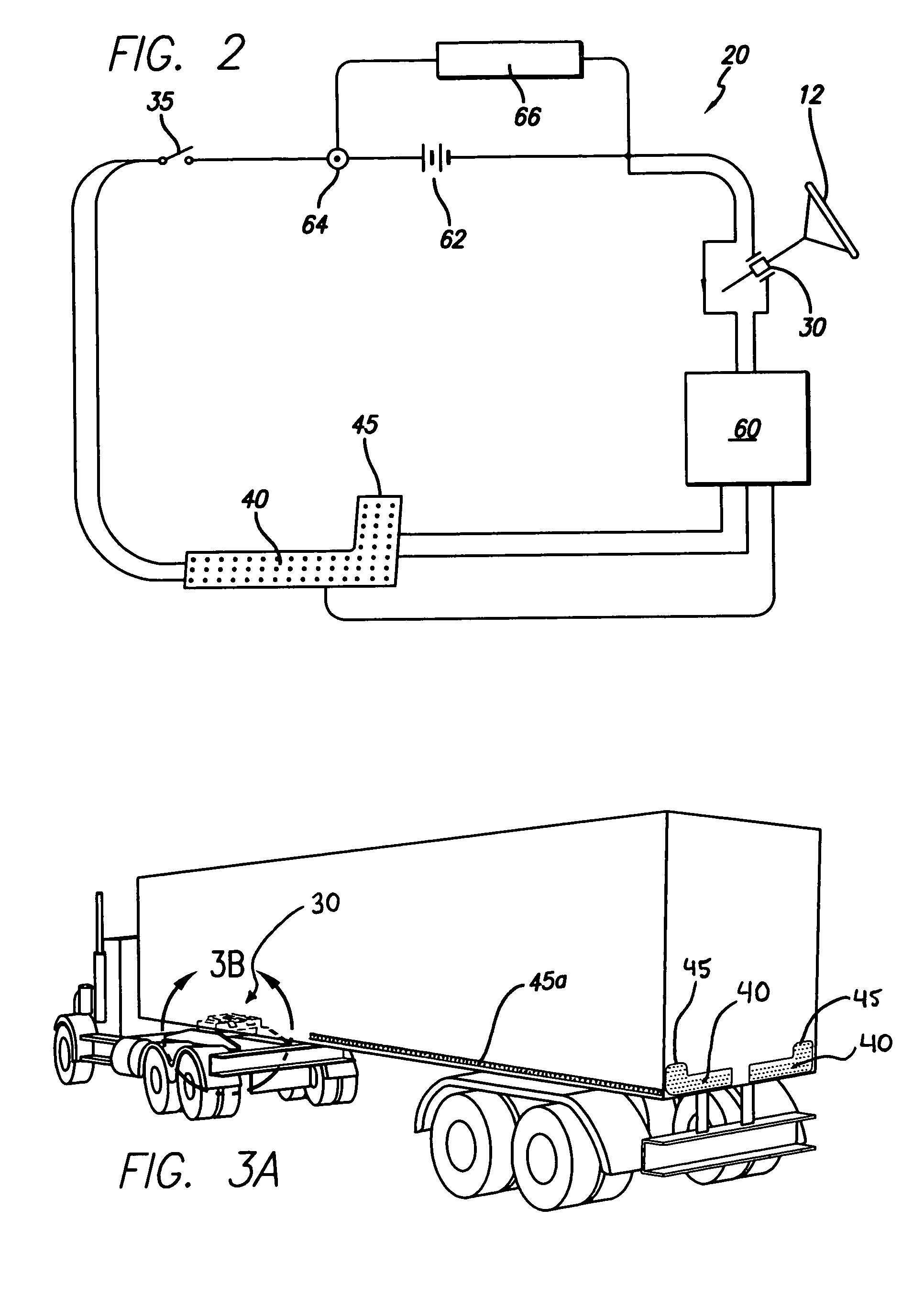
[0020]One embodiment of the present invention is illustrated in FIGS. 1a, 1b, and 2. This embodiment is a turn signaling system 20 comprising one or more first detectors 30 in communication with signaling lights 40 in turn signal panels 45 mounted on a vehicle 10. The system is turn-proportioned such that it can provide type-specific n...


PUM


Abstract

A turn proportioned turn signaling system for vehicles. The lamp arrays are provided signals from rotary sensors 30 from the steering column, the rack and pinion gear system, or trailer hitch mechanism that either directly affect the signaling pattern or drive a logic control unit that in turn drives the signaling pattern. The signal display panels may consist of a plurality of lamps or light emitting diodes intended to alert the surrounding people and vehicles. The display pattern selected by the logic control unit depends the magnitude and rate of turn.

Description

BACKGROUND OF THE INVENTION[0001]1. Field of the Invention[0002]This invention relates to sets of lights that are arranged on an external surface of an automobile or vehicle to communicate a signal to other drivers and pedestrians and in particular to such light devices that capable of illuminating in dynamic patterns to enhance the information communicated to others.[0003]2. Description of the Related Art[0004]Currently, turn signals on vehicles typically consist of one or more lamps or light bulbs and flash in well-established constant time intervals. The flashing light bulbs indicate the direction of turn by the sheer position of the flashing lamp in relation to the center of the vehicle. That is, information that the vehicle is turning or is about to turn to the right is communicated to other drivers and pedestrians by a flashing turn signal light located on the right-hand side of the vehicle, ordinarily both on the front-right corner of the vehicle and on the rear-right corner ...

Claims


Application Information

Patent Timeline
Patent Type & Authority Patents(United States)
IPC IPC(8): B60Q1/34B60Q1/38
CPCB60Q1/346B60Q1/38B60Q1/381
Inventor SUBBARAMAN, RAMESH
Owner SUBBARAMAN RAMESH
Learn More