Wireless integrated occupancy sensor

a sensor and occupancy technology, applied in the field of occupancy sensors, can solve the problems of insufficient accuracy of inability to accurately indicate the occupancy of rooms, and inability to use pir motion detectors as occupancy sensors,

Inactive Publication Date: 2006-10-17
TAK AB
View PDF8 Cites 76 Cited by
  • Summary
  • Abstract
  • Description
  • Claims
  • Application Information

AI Technical Summary

Problems solved by technology

However, the use of a PIR motion detector as an occupancy sensor does not produce an accurate indication of a room being occupied in situations in which an occupant remains motionless for an extended period of time, such as in sleeping, reading or watching television.
The PIR motion detector is also not accurate in rooms in which the geometry of the room includes blind spots to the PIR motion detector such as alcoves or bathrooms.
This wiring is in many cases prohibitively expensive.
This method mitigates, but does not completely solve, the cost of the additional wiring to install apparatus.
It also does not address the case in which an individual thermostat is not needed in each room.
However, the separate components may be more noticeable to occupants of the room, and this system requires installation of multiple components in each room, and the changing of different types of batteries in the different components at different intervals, increasing expenses.

Method used


Image

  • Wireless integrated occupancy sensor
  • Wireless integrated occupancy sensor
  • Wireless integrated occupancy sensor

Examples


Embodiment Construction

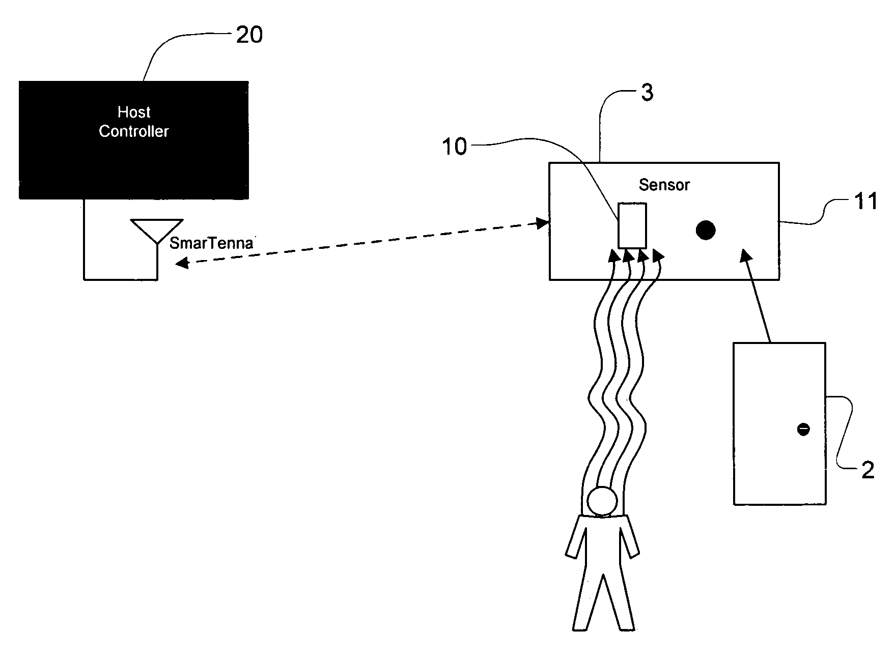
[0017]The present invention is a battery-powered, wireless integrated occupancy sensor. In one embodiment, it is a small battery operated sensor to be used to determine if a controlled space, such as a room, is occupied. It will be used in conjunction with a fixed algorithm or programmable processor used as the controller of HVAC equipment, with which it will be in wireless communication, that needs occupancy information to optimize energy use in HVAC operations.

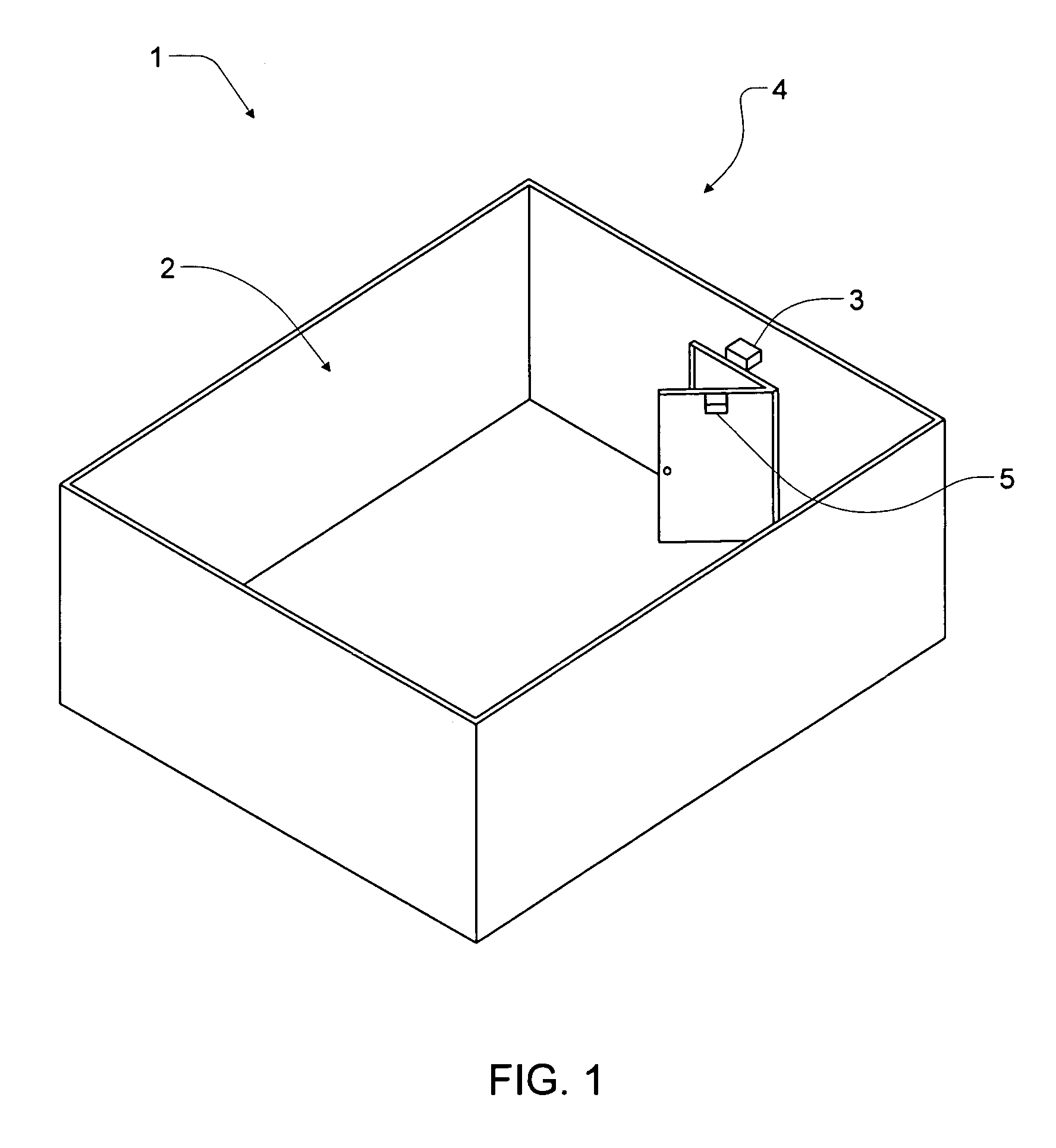
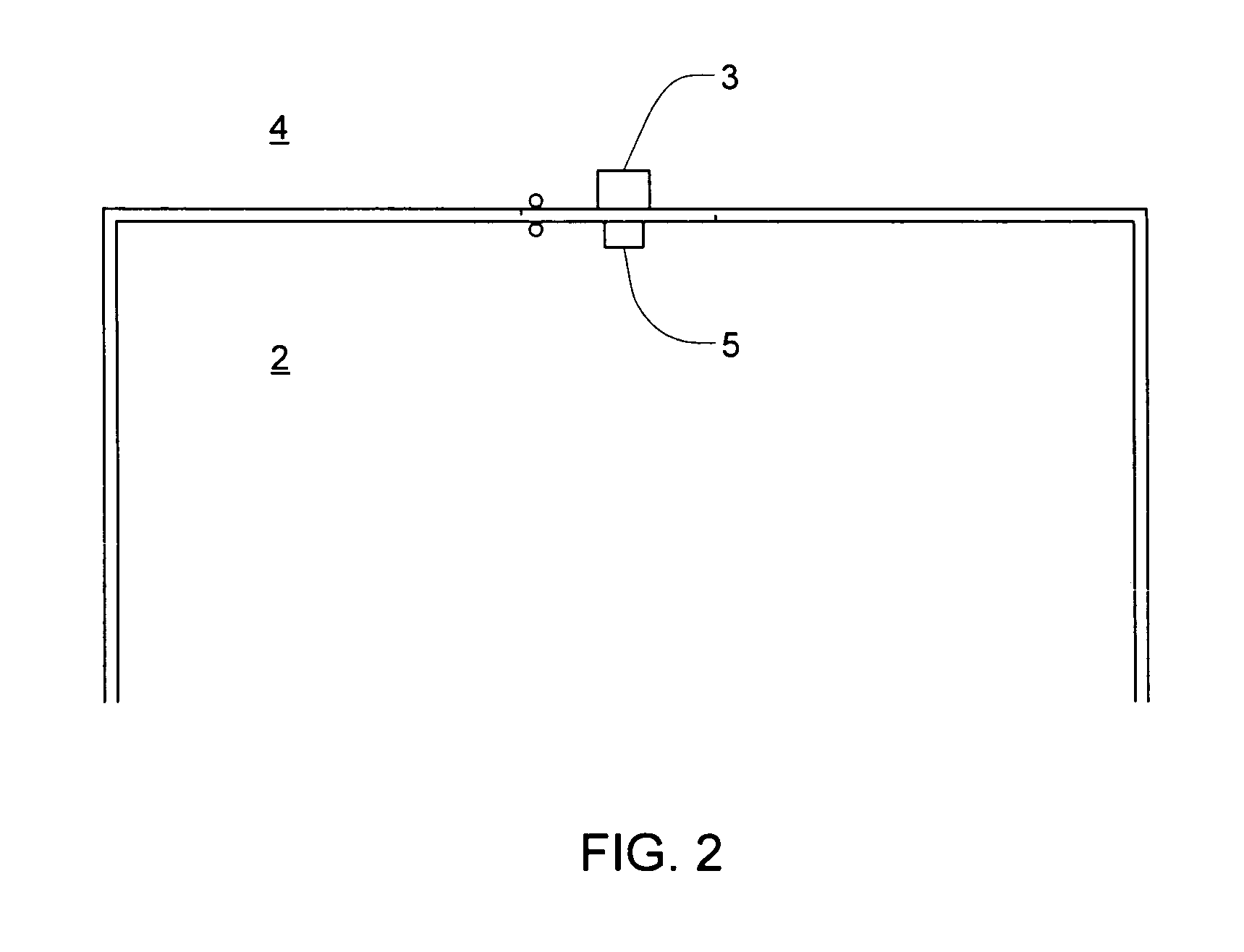
[0018]In one embodiment, as shown in FIG. 1, occupancy information is sought for a controlled space such as a room 1, with access door 2. The occupancy sensor 3 of the present invention is mounted on the door frame 4 holding door 2. A small magnet 5 is mounted on door 2 in proximity to the occupancy sensor 3 when door 2 is shut. A closer view of the door 2 and door frame 4 is shown in FIG. 2, which also shows the occupancy sensor 3 mounted on the door frame 4 and the small magnet 5 mounted on the door 2.

[0019]Another embodim...


PUM


Abstract

An occupancy sensor is provided for determining whether a room is occupied. The occupancy sensor integrates a battery-powered PIR motion detector and a battery-powered Hall Effect switch, each of which communicates wirelessly with a controller, in a single housing.

Description

CROSS-REFERENCE TO RELATED APPLICATIONS[0001]The present application claims the benefit of application Ser. No. 60 / 574,198 filed May 25, 2004, which is incorporated herein by reference.TECHNICAL FIELD[0002]The present application relates to an occupancy sensor for a room and, in particular, to an occupancy sensor that integrates a passive infrared (“PIR”) motion detector and a magnetic door switch in one wireless, battery-powered unit.BACKGROUND OF THE INVENTION[0003]Many building owners, including the owners of apartments, offices and hotels, continue to seek methods to decrease their heating, ventilating and cooling (“HVAC”) expenses. One method to do so is to select minimum and maximum setback temperatures for a room, which require less operation of the room's HVAC equipment, when the room is not occupied. This method requires an accurate occupancy sensor for the room.[0004]In the past, motion detectors have been used as occupancy sensors. In particular, PIR motion detectors have...

Claims


Application Information

Patent Timeline
Patent Type & Authority Patents(United States)
IPC IPC(8): G08B19/00F24F11/00G08B13/19G08B29/18
CPCF24F11/0034G08B13/19G08B19/00G08B29/183F24F11/30F24F2120/10F24F11/46
Inventor SWEENEY, KEVIN
Owner TAK AB
Why Eureka
Try Eureka