
Image forming device operatively configurable in accordance with aural conditions in the vicinity thereof

a technology aural conditions, which is applied in the field of image forming device, can solve the problems of difficult to completely prevent the aforementioned noise from being generated, difficult to completely prevent the noise from leaking out of the image forming device, and difficult to hear the voice of another person over the telephone or during, etc., and achieves the effect of being easily heard by a user

Inactive Publication Date: 2006-10-17
KYOCERA DOCUMENT SOLUTIONS INC
View PDF7 Cites 1 Cited by
  • Summary
  • Abstract
  • Description
  • Claims
  • Application Information

AI Technical Summary

Benefits of technology

[0009]Accordingly, it is an object of the present invention to provide an image forming device that does not disturb those inside an office with noise generated during printing and the like, and which generates notification sounds that can be easily heard by a user.
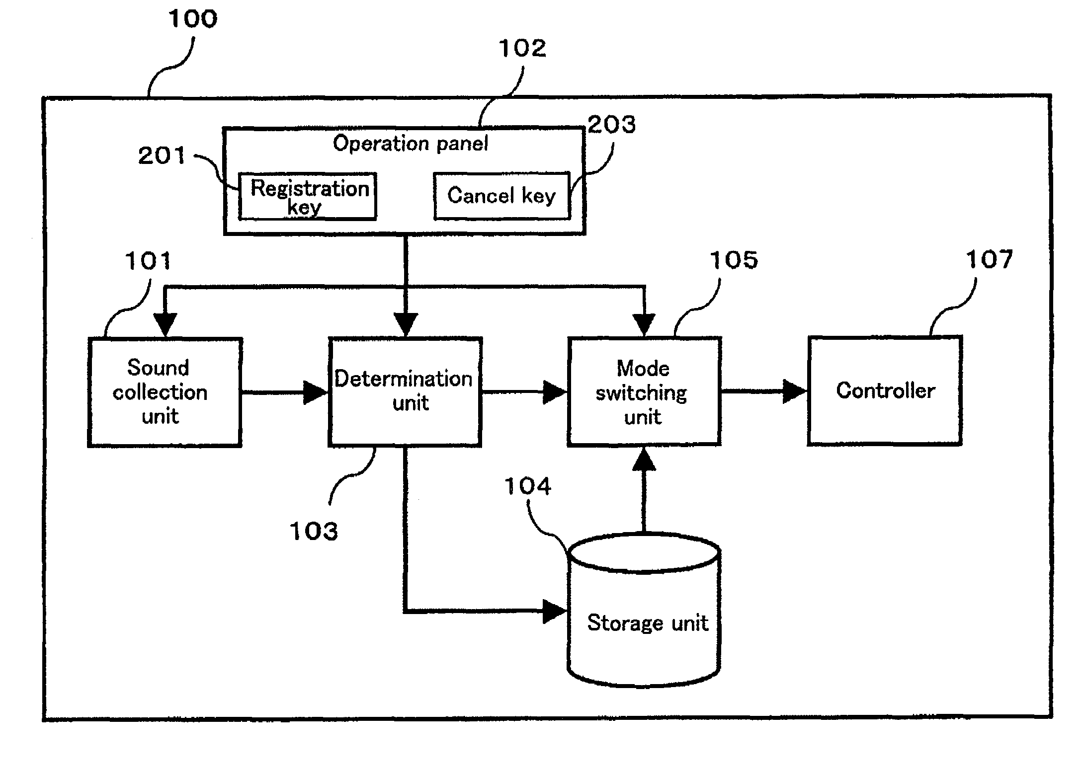
[0012]For example, if there is a sound that is difficult to hear due to noise generated by printing, the user will collect that sound with the sound collection unit, and the characteristic of that sound will be determined by the determination unit and then be stored in the storage unit. Then, if the characteristic of a sound collected by the sound collection unit is the same as or similar to the characteristic of one or more of the sounds stored in the storage unit, the mode switching unit will switch to an operation mode that reduces the noise of printing. This will eliminate disturbances to work being performed in the vicinity of the image forming device that are caused by noise generated when printing.
[0013]In addition, in order to prevent notification sounds generated by the image forming device from being drowned out by sounds generated in the vicinity of the image forming device, the mode switching unit will switch to an operation mode that can generate notification sounds (sounds used to notify a user of the image forming device) having characteristics that are different from the characteristic of a sound collected by the sound collection unit.

Problems solved by technology

Because of that, it will be difficult to hear another person's voice over the telephone or during a face-to-face conversation if, for example, these conversations occur in the vicinity of an image forming device performing these types of operations.
However, it is difficult to completely prevent the aforementioned noise from being generated, and also difficult to completely prevent this noise from leaking out of the image forming device.
In addition, the cost of the image forming device will increase if a configuration that improves the soundproofing capabilities thereof or suppresses the generation of noise therein is adopted.
However, there are times in which these notification sounds will be drowned out by the background noise of the office because they are not loud enough.
Thus, when background noise is being generated in the office, there will be times when, for example, the user will not be able to recognize that an operation key has been pushed, will not notice that data has been received by facsimile, or will not notice that the device has run out of paper.

Method used


Image

  • Image forming device operatively configurable in accordance with aural conditions in the vicinity thereof
  • Image forming device operatively configurable in accordance with aural conditions in the vicinity thereof
  • Image forming device operatively configurable in accordance with aural conditions in the vicinity thereof

Examples


first embodiment

1. First Embodiment

[0021]As shown in FIG. 1, an image forming device 100 of the present invention includes a sound collection unit 101. When each key displayed on an operation panel 102 provided on an upper surface of the image formation device 100 is pressed, a command corresponding to each key pressed will be input into the sound collection unit 101.

[0022]The sound collection unit 101 collects sound only when a registration key 201 displayed on the operation panel 102 is pressed, and when the sound collection unit 101 is supplied with electrical power, i.e., is turned on (FIG. 3, S301–S302).

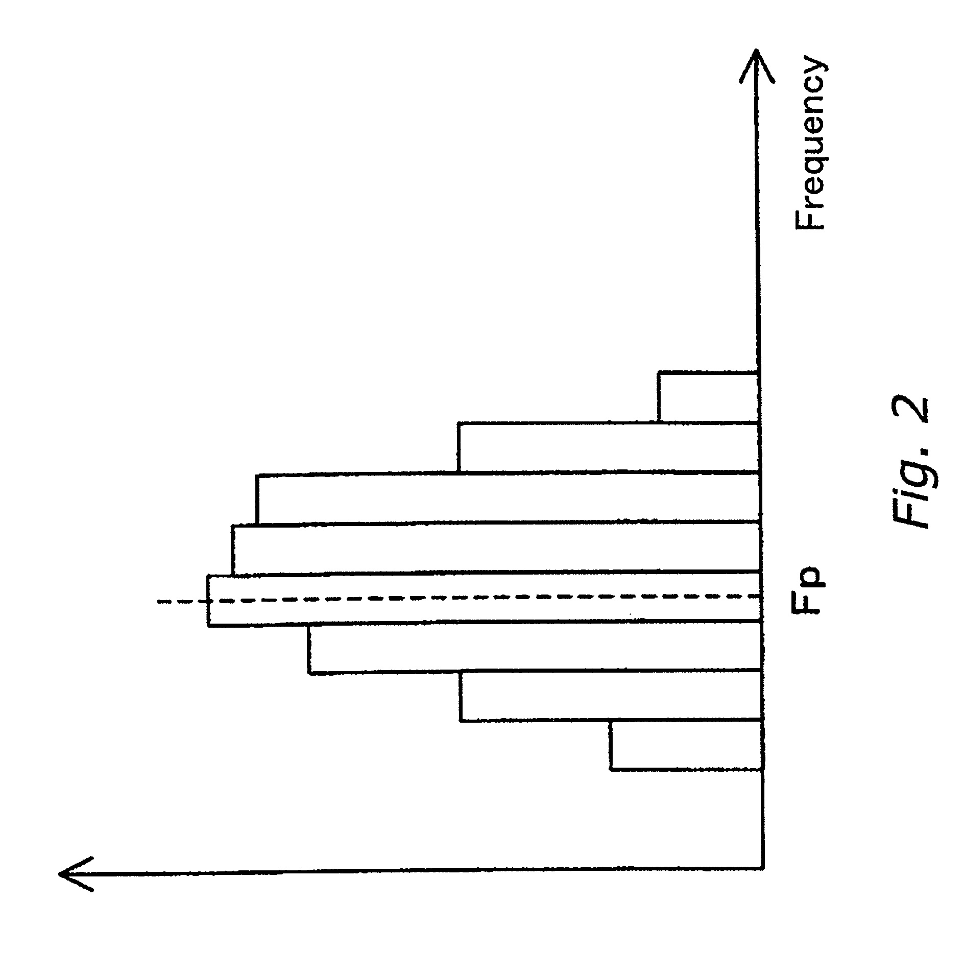
[0023]Sound collected by the sound collection unit 101 is input into a determination unit 103. The determination unit 103 determines the characteristics of the sound input therein. The determination unit 103 performs an analog to digital (A / D) conversion on sound input therein in order to determine the characteristics of the sound. After the A / D conversion, the determination unit 103 will deter...

second embodiment

2. Second Embodiment

[0053]Rather than just one type of quiet mode noted above, there may instead be a plurality of quiet modes. For example, if company employee A's desk is near the image forming device 100 and company employee B's desk is far away from the image forming device 100, the volume of the sound generated by the image forming device 100 will be lower at Mr. B's desk than it will be at Mr. A's desk. Thus, when Mr. B's voice is collected, the mode switching unit 105 can select a corresponding operation mode having a printing speed that is faster than when Mr. A's voice is collected.

[0054]In this situation, when the user stores a sound in the storage unit 104, the operation modes that can be selected when the characteristics of that sound are input into the mode switching unit 105 will also be stored in the storage unit 104.

[0055]For example, if the determination unit 103 determines the characteristics of an input sound as described above in the first embodiment, then, as sh...


PUM


Abstract

An image forming device is disclosed which collects sounds in the vicinity of the image forming device, and then determines the characteristics of the collected sounds. The image forming device will then select an operation mode based upon the characteristics of the collected sounds, and will generate notification sounds and operate in accordance with the selected operation mode.

Description

BACKGROUND OF THE INVENTION[0001]1. Field of the Invention[0002]The present invention relates to an image forming device such as a copying machine, a digital multi-functional device, a printer, and the like.[0003]2. Background Information[0004]Image forming devices such as copying machines, digital multi-functional devices, printers, and the like are now widely used in offices. When these types of image forming devices perform tasks such as copying original documents and printing data received by facsimile, noises will be generated thereby such as the sound of the transfer drum rotating and the sound of paper being transported, printed and discharged.[0005]Because of that, it will be difficult to hear another person's voice over the telephone or during a face-to-face conversation if, for example, these conversations occur in the vicinity of an image forming device performing these types of operations.[0006]In response to this problem, image forming devices that, for example, are abl...

Claims


Application Information

Patent Timeline
IPC IPC(8): G03G15/00B41J29/38G03G21/00G10L15/00G10L15/10G10L17/00G10L17/02G10L17/26H04N1/00
CPCG03G21/00
Inventor ANDOU, HIRONORI
Owner KYOCERA DOCUMENT SOLUTIONS INC
Learn More