Muntin bar connector with positioning tabs

a technology of positioning tabs and connectors, applied in the field of windows, can solve the problems of broken seals in insulated glass packs, many holes in window frames or glass frames, and high labor intensity

Inactive Publication Date: 2006-10-24
PELLA
View PDF27 Cites 44 Cited by
  • Summary
  • Abstract
  • Description
  • Claims
  • Application Information

AI Technical Summary

Problems solved by technology

A problem with the prior art approach was that it required the drilling of many holes in the window frame or glass frame.
This involved much labor and could lead to broken seals in insulated glass packs.

Method used


Image

  • Muntin bar connector with positioning tabs
  • Muntin bar connector with positioning tabs
  • Muntin bar connector with positioning tabs

Examples


Embodiment Construction

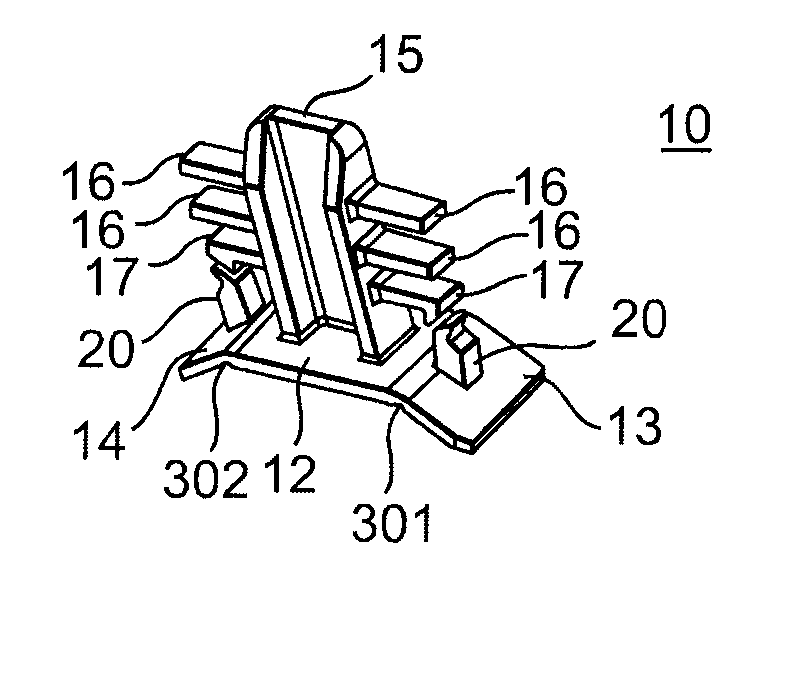
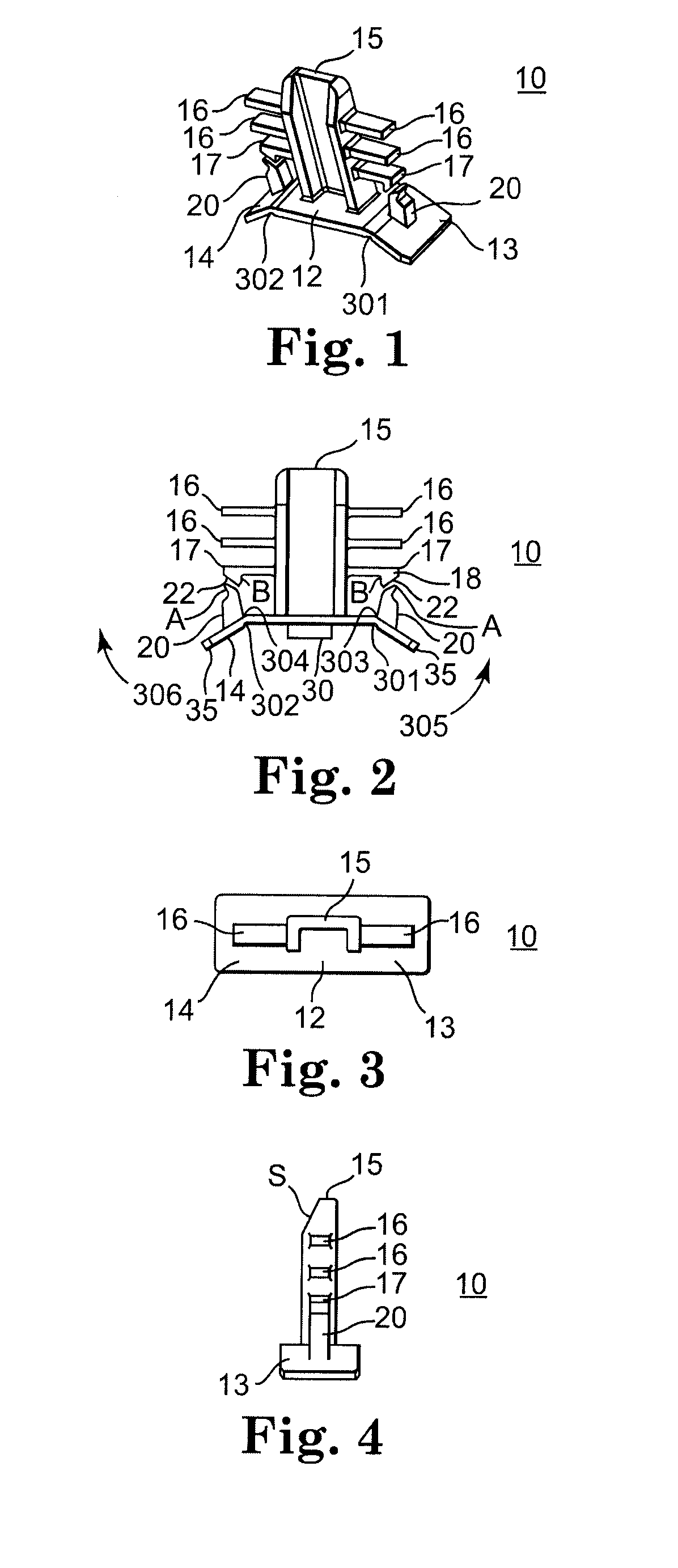
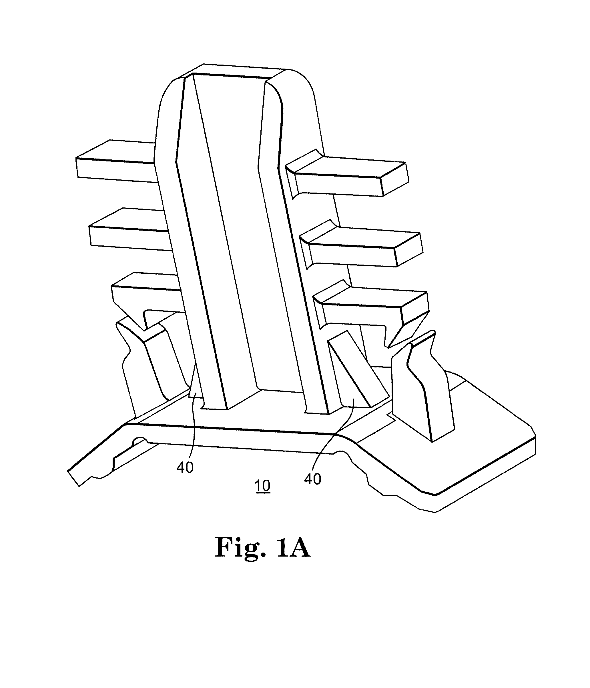
[0023]Referring now to FIGS. 1 and 2, thereshown is a connector 10 of the present invention. Connector 10 includes baseplate 12 and muntin bar tab 15. In use, the muntin bar tab is connected to a muntin bar (see FIG. 7D for an example) and the baseplate is mounted on a window frame.

[0024]The muntin bar tab in this embodiment is generally a rectangular prism extending from the baseplate. It is advisable to make the size and shape of the baseplate at least generally match the shape of the cavity into which it will be inserted and preferably make the surface area large enough to cover the entire opening. The baseplate includes first and second positioning tabs 13 and 14. The positioning tabs can be formed by forming narrowed regions 301 and 302, of the baseplate. A resilient effect is generated when positioning tab 13 is moved in the direction of arrow 305. Region 303 is compressed in such a movement and provides the spring force to return the tab to a downward orientation. Region 304 ...


PUM


Abstract

A connector for holding an internal muntin assembly away from a perimeter spacer of an insulating glass assembly until the assembler is ready to affix the muntin bar to the perimeter bar using an attachment device. The connector includes a positioning tab for holding the muntin bar away from the perimeter spacer to allow positioning of the muntin bar assembly until the positioning tab is moved relative to a baseplate so that the attachment device, such as thick double stick tape, is pressed to the perimeter spacer.

Description

TECHNICAL FIELD[0001]The present invention relates to the field of windows and more specifically to the field of grills for windows.BACKGROUND OF THE INVENTION[0002]It has become a design trend for windows to include a grill to enhance the aesthetic look of the window. For example, U.S. Pat. No. 3,686,814 (Anderson) shows false muntin bars 20 and 22 positioned on a window.[0003]Many different methods of attaching the grills to the window frame were developed. In U.S. Pat. No. 5,657,590 (Digman et al.), an end connector was shown (see FIGS. 3 and 4) for connecting a muntin bar to a window frame (see FIG. 1). The end connector included a spine, a stabilizing end, fins, a platform 38 and pins. The stabilizing end was inserted into open ends of the muntin bar and engaged with the holes to hold the bar in place. End connectors in U.S. Pat. No. 5,678,376 (Poma) and U.S. Pat. No. 6,425,221 (Reichert) operated in a similar manner.[0004]A problem with the prior art approach was that it requi...

Claims


Application Information

Patent Timeline
Patent Type & Authority Patents(United States)
IPC IPC(8): B44F7/00E06B3/66E06B3/667
CPCE06B3/6604E06B3/667E06B3/6675
Inventor SCHARFF, JOHN WAYNESCHNEIDER, LAWRENCE A.
Owner PELLA
Why Eureka
Try Eureka