Chassis air guide thermal cooling solution

a technology of air guide and thermal cooling solution, which is applied in the direction of power cables, cables, semiconductor/solid-state device details, etc., can solve problems such as dissipation effects

Inactive Publication Date: 2006-10-24
LIANG HSIEN RONG
View PDF11 Cites 24 Cited by
  • Summary
  • Abstract
  • Description
  • Claims
  • Application Information

AI Technical Summary

Benefits of technology

[0009]The invention is characterized that, protruding edges E1 of the fan E are wedged at wedge grooves D2 of the locating assembly D to locate the fan E in the locating assembly D, locating notches F1 of the flexible ring F are positioned in the locating assembly D, the accommodating ring G is accommodated around the flexible ring F, and the locating assembly D is fastened with the locating plate C by means of screws; and the side panel B is devised with ventilation openings B1 for facilitating the fan E to draw external air or to discharge hot air in an interior of the device.

Problems solved by technology

Supposed that the interior accommodates numerous devices, heat dissipating effects are further lowered, and hence damages are likely resulted in case that the devices are precision equipments.

Method used


Image

  • Chassis air guide thermal cooling solution
  • Chassis air guide thermal cooling solution
  • Chassis air guide thermal cooling solution

Examples


Embodiment Construction

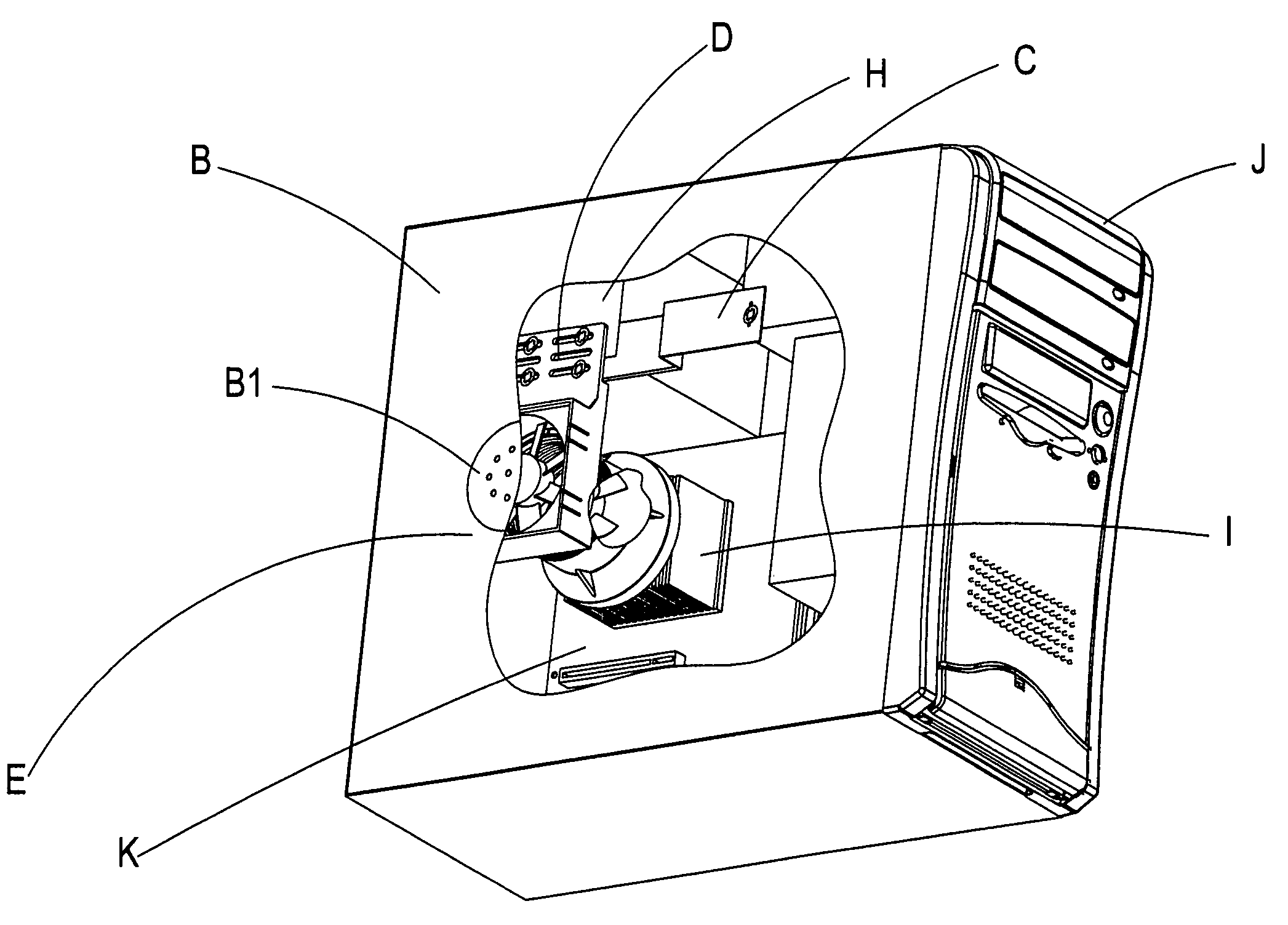
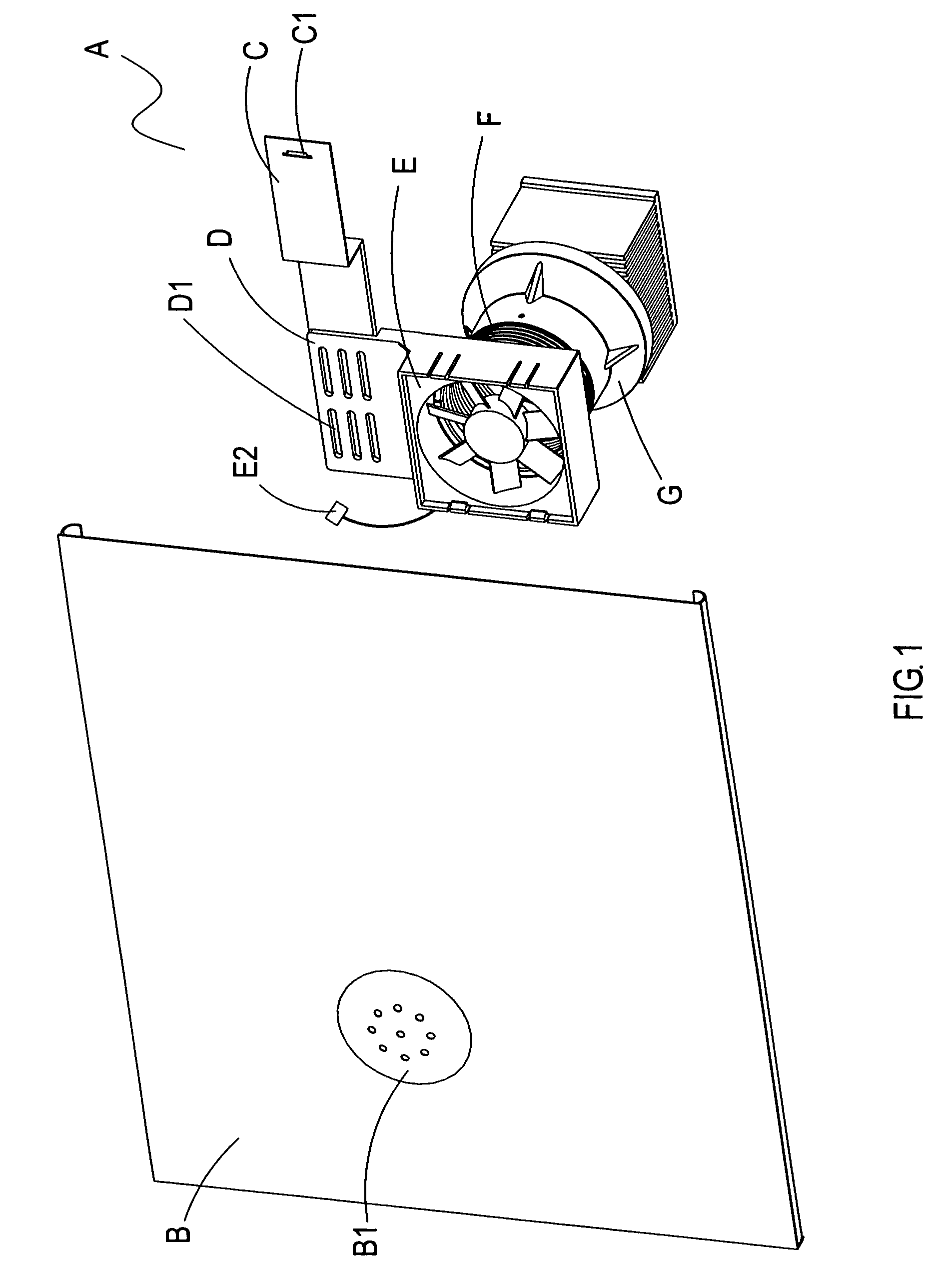
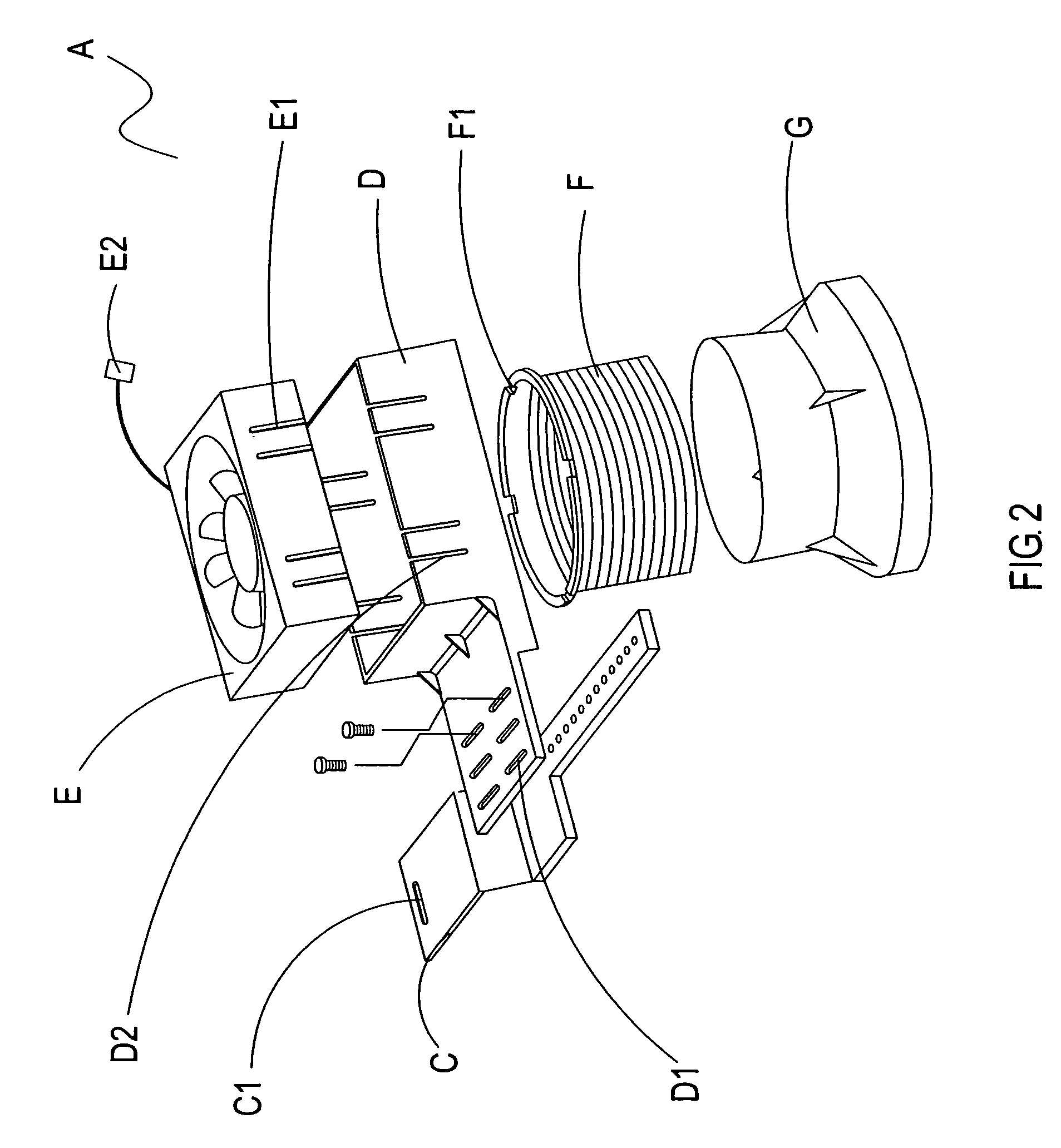
[0023]Referring to FIGS. 4, 4-1 and 4-2 showing an embodiment of a chassis air guide thermal cooling solution according to the invention, a motherboard D at an interior of a computer host J is provided with cooling fins I and a heat dissipating fan L.

[0024]The wedge opening C1 of the locating plate C is fixed to the interior of the computer host J using a screw. The flexible openings D1 of the locating assembly D are fixed with the locating plate C and the power supply H using screws. The fan E is connected with a power line H1 of the power supply H via a power line E2.

[0025]During operation of the computer host, for that the accommodating ring G is accommodated around the heat dissipating fan L, when the heat dissipating fan L blows air at the cooling fins I, cold air from an exterior is drawn by the flexible ring F and the fan E via the ventilation openings B1 at the side panel B. Thus, hot air at the interior of the device is not sucked in by the heat dissipating fan L to prevent...


PUM

PropertyMeasurementUnit
flexibleaaaaaaaaaa
lengthaaaaaaaaaa
dimensionsaaaaaaaaaa

Abstract

A chassis air guide thermal cooling solution including a fan to which protruding edges are wedged at wedge grooves of a locating assembly to locate the fan therein, locating notches of a flexible ring are positioned in the locating assembly, an accommodating ring is accommodated around the flexible ring, and the locating assembly is fastened with a locating plate by means of screws; a side panel is devised with ventilation openings for drawing external air or discharging hot air at the interior of the device. The locating assembly is provided with a plurality of flexible openings, and after having fixed the locating plate therein, an assembled position of the chassis air guide thermal cooling solution is adjusted; after having assembled the chassis air guide thermal cooling solution therein, a distance between the accommodating ring and the heat dissipating fan is adjusted using the flexible ring.

Description

BACKGROUND OF THE INVENTION[0001](a) Field of the Invention[0002]The invention relates to a chassis air guide thermal cooling solution. More particularly, to a chassis air guide thermal cooling solution characterized that, protruding edges of a fan are wedged at wedge grooves of a locating assembly to locate the fan in the locating assembly, locating notches of a flexible ring are positioned in the locating assembly, an accommodating ring is accommodated around the flexible ring, and the locating assembly is fastened with a locating plate by means of screws; a side panel is devised with ventilation openings for facilitating the fan to draw external air or to discharge hot air in an interior of the device; and the locating assembly is provided with a plurality of flexible openings.[0003]To assemble the chassis air guide thermal cooling solution, after having fixed the locating plate to the interior of the device, an assembled position of the chassis air guide thermal cooling solution...

Claims


Application Information

Patent Timeline
Patent Type & Authority Patents(United States)
IPC IPC(8): H05K7/20F28F7/00G06F1/20H01B9/06H01L23/34
CPCG06F1/20H05K7/20172
Inventor LIANG, HSIEN-RONG
Owner LIANG HSIEN RONG
Why Eureka
Try Eureka