Device for treating intervertebral disc herniations
a technology of disc anthroplasty and disc herniation, which is applied in the field of distraction disc anthroplasty device and method for treating intervertebral disc herniation, can solve the problems of ignoring several procedural variables, major source of back pain, pain and numbness in the leg, feet and arms of affected patients, and the use of prior art devices, so as to distract the cavity space, short-term recovery, and source of back pain
- Summary
- Abstract
- Description
- Claims
- Application Information
AI Technical Summary
Benefits of technology
Problems solved by technology
Method used
Image
Examples
embodiment 30
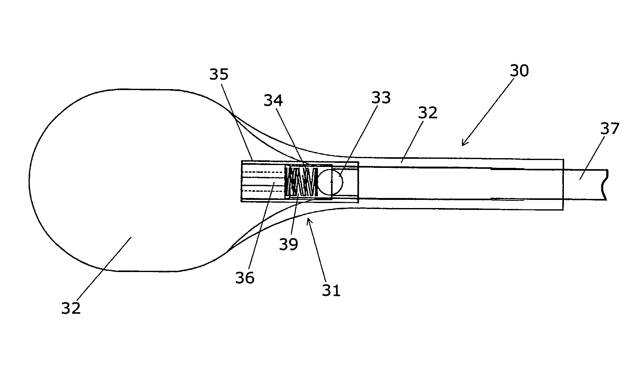
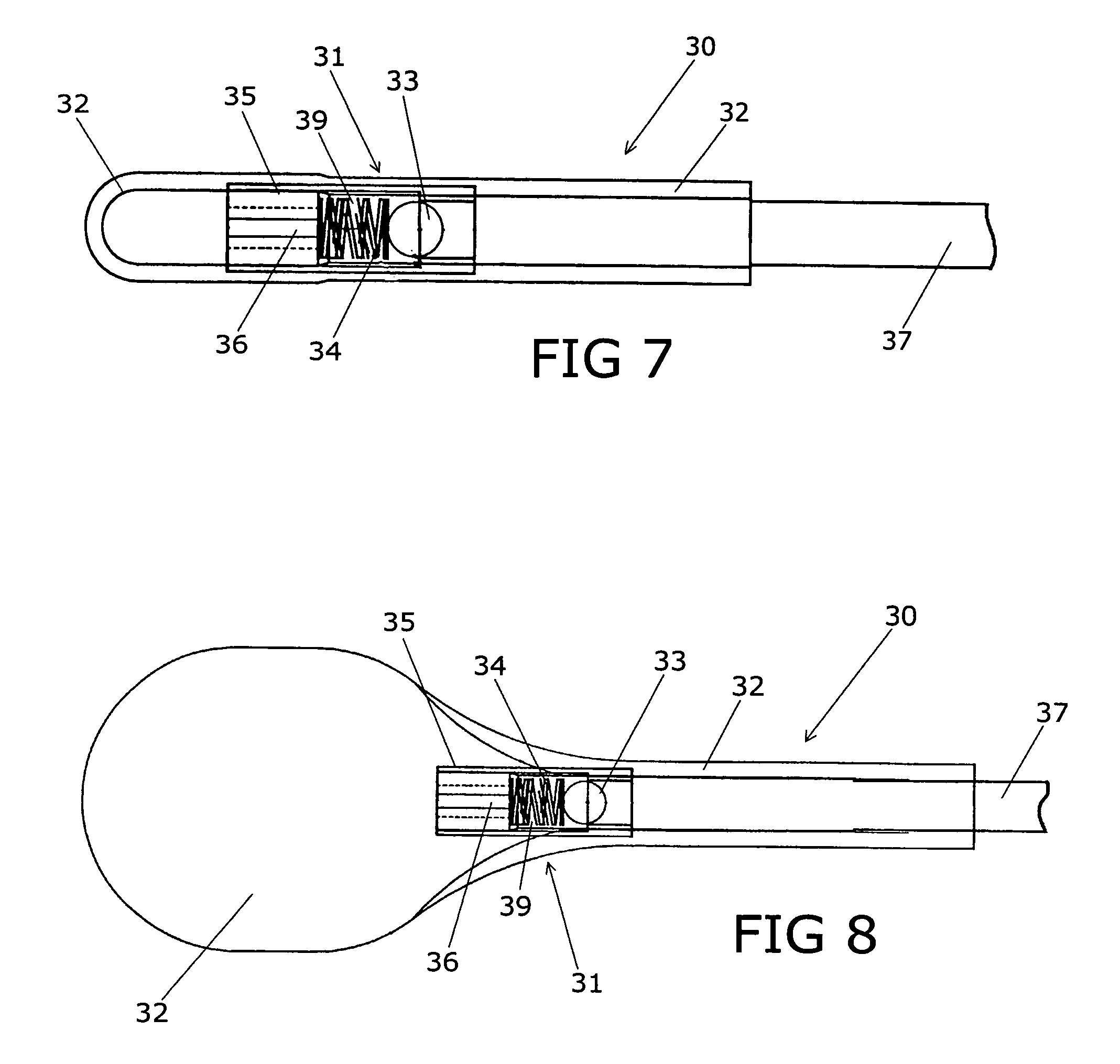
[0038]As shown in FIG. 7, the inflatable balloon device embodiment 30 of the invention comprises a rigid body portion 31 and a flexible balloon member 32. The rigid body portion 31 is shown having a valve chamber 39 containing a ball valve member 33, a biasing spring member 34, and a valve plug portion 35 positioned at one end. The valve plug portion 35 is shown having slots 36, which are constructed and arranged to allow the passage of fluid. A fill tube 37 is shown extending from the opposite end of rigid body portion 31 and is constructed and arranged to provide fluid flow through the valve plug 35 in order to inflate and deflate the balloon member 32. The ball valve member 33 is constructed and arranged to seal the fill tube 37 due to the pressure created from the spring 34 and internal pressure of the balloon member 32. FIG. 8 shows the balloon member 32 in an inflated state. In the inflated or expanded state, the balloon member 32 is shown separated from a portion of the valve...
embodiment 40
[0039]As shown in FIGS. 9 and 10, an alternate valve body embodiment 40 is shown having a valve body structure 41 having opposing ends 42 and 43. The valve body 41 has a valve chamber 44, which begins at the internally sloped valve seat 45. FIGS. 11 and 12 show valve end plug 46 which is shown inserted in end 42 of the valve body 41. The end plug 46 has a plurality of slots or channels 47 which permits the passage of fluid as described above. The end plug may be threaded into or otherwise secured in the end of the valve body 41. Although the slots or channels 47 are shown peripherally located on the end plug 46, the channels may extend through the end plug body.
[0040]FIGS. 13 and 14 show the assembled valve body 50 having ball valve 33 located in the sloped valve seat 45 and the biasing spring member 34 positioned between the end plug 46 and the ball valve 33. In a similar manner, as described above, the fill tube 37 is inserted and secured in the end portion 43 of the valve body 41...
PUM
| Property | Measurement | Unit |
|---|---|---|
| diameter | aaaaa | aaaaa |
| diameter | aaaaa | aaaaa |
| internal diameter | aaaaa | aaaaa |
Abstract
Description
Claims
Application Information
 - R&D
- Intellectual Property
- Life Sciences
- Materials
- Tech Scout
- Unparalleled Data Quality
- Higher Quality Content
- 60% Fewer Hallucinations
Browse by: Latest US Patents, China's latest patents, Technical Efficacy Thesaurus, Application Domain, Technology Topic, Popular Technical Reports.
© 2025 PatSnap. All rights reserved.Legal|Privacy policy|Modern Slavery Act Transparency Statement|Sitemap|About US| Contact US: help@patsnap.com


