Compressor

Inactive Publication Date: 2011-05-26
LG ELECTRONICS INC
View PDF45 Cites 2 Cited by
  • Summary
  • Abstract
  • Description
  • Claims
  • Application Information

AI Technical Summary

Benefits of technology

[0046]The compressor having the above configuration in accordance with the present invention is advantageous in that it not only enables compact design with a minimal height and reduced size of the compressor by radially arranging the compression mechanism and the electromotive mechanism to define the compression chamber inside the compressor by the rotor of the electromotive mechanism, but it also minimizes frictional loss on account of a substantially reduced relative velocity difference between the cylinder type rotor and the roller by compressing refrigerant in the compression chamber between the rotor and the roller through the rotational force that is transferred to the roller from the rotating rotor, thereby maximizing the compressor efficiency.
[0047]Moreover, since the vane defines the compression cha

Problems solved by technology

Although the reciprocating compressor is excellent in mechanical efficiency, its reciprocating motion causes serious vibrations and noise problems.
A high relative velocity is created between constituent elements making a sliding contact with each other, and this generates frictional loss, eventually leading to degradation of compressor efficiency.
Also, there is still a possibility of a refrigerant leak at the contact surface between the vane and the roller, thereby causing degradation of mechanical reliability.
However, even in this patent, the stationary shaft still makes a sliding contact with an interior surface of the roller so a hig

Method used


Image

  • Compressor
  • Compressor
  • Compressor

Examples


Embodiment Construction

[0060]Hereinafter, preferred embodiments of the present invention will be described in detail with reference to the accompanying drawings.

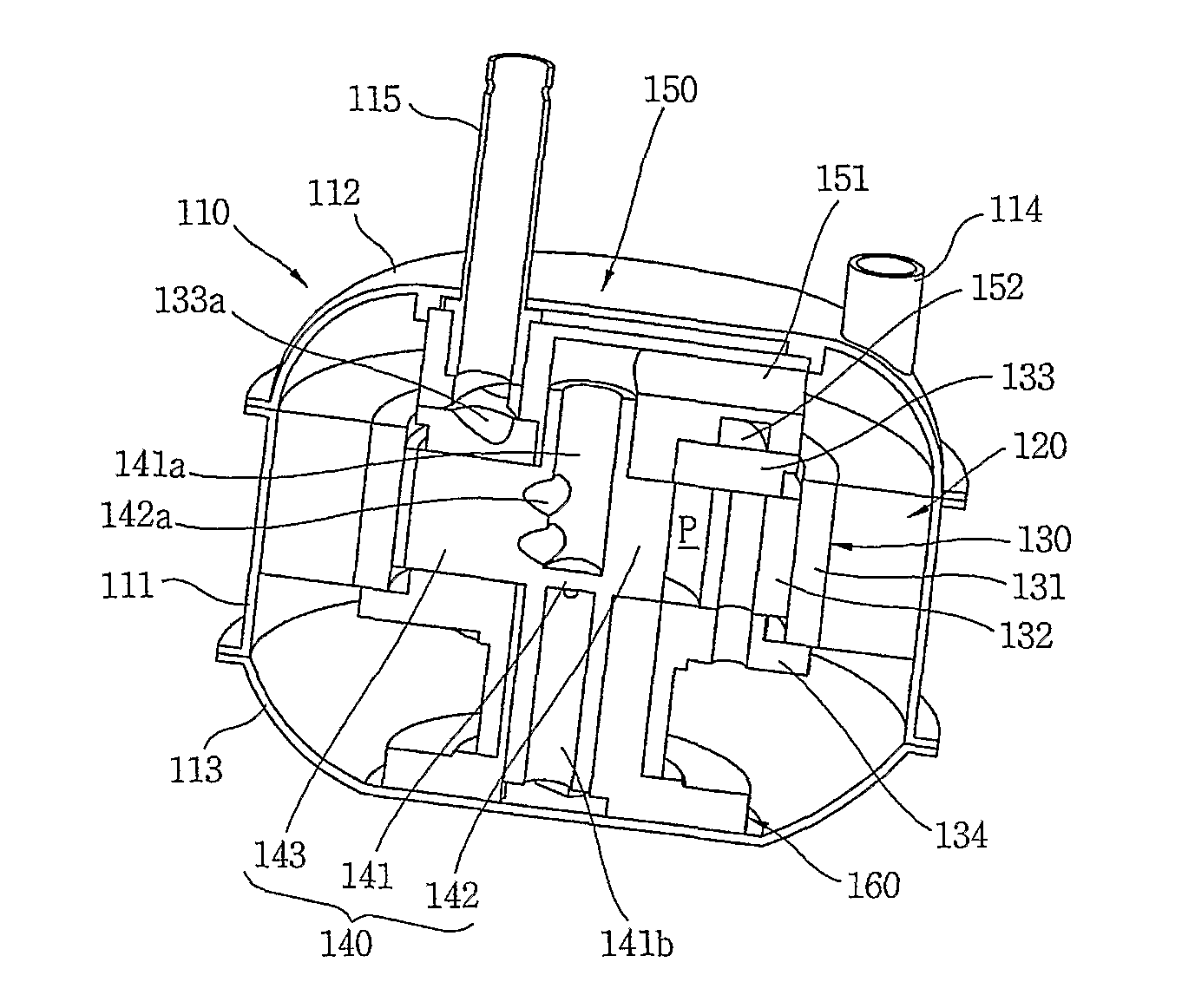
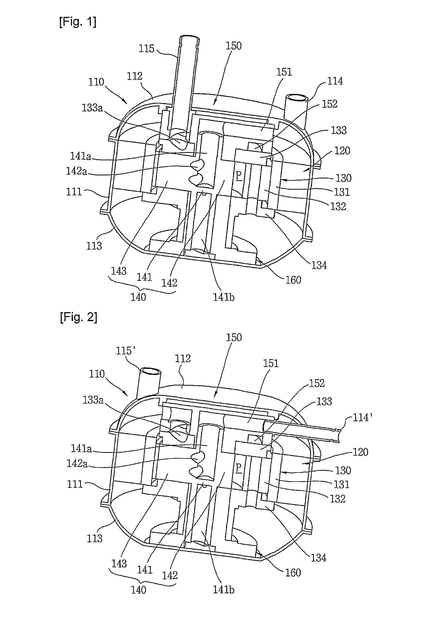
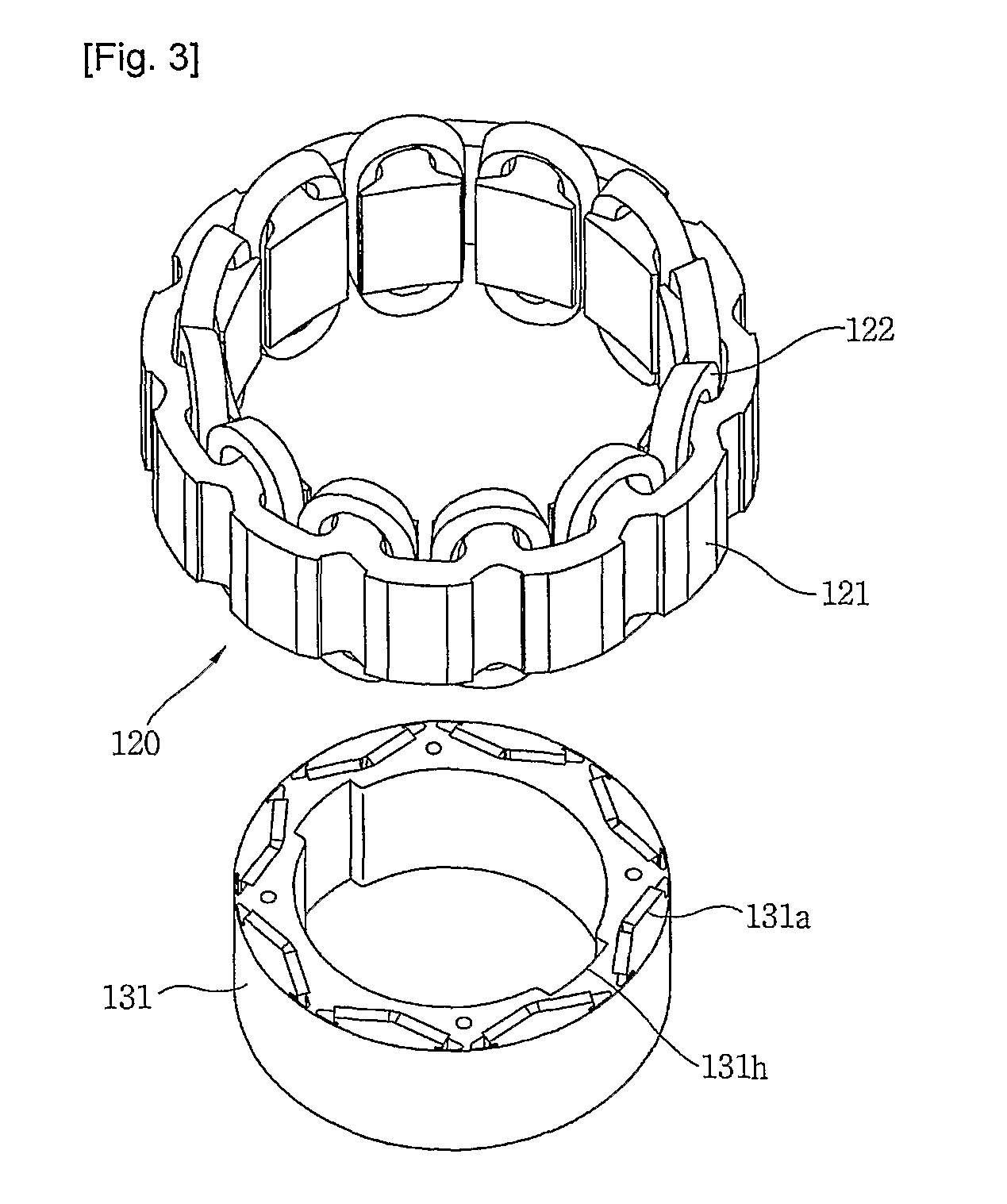
[0061]FIG. 1 is a transverse cross-sectional view showing a compressor in accordance with a first embodiment of the present invention, FIG. 2 is a transverse cross-sectional view showing a compressor in accordance with a second embodiment of the present invention, FIG. 3 is an exploded perspective view showing one example of an electric motor of the compressor in accordance with one embodiment of the present invention, and FIGS. 4 and 5 each illustrate an exploded perspective view showing one example of a compression mechanism part of the compressor in accordance with one embodiment of the present invention.

[0062]As shown in FIG. 1, a compressor in accordance with first and second embodiments of the present invention includes a hermetic container 110, a stator 120 installed within the hermetic container 110, a first rotating member 130 installed w...


PUM


Abstract

The present invention provides a compressor, comprising a stator (120); a cylinder type rotor (131) rotating within the stator (120) by a rotating electromagnetic field from the stator (120), with the rotor defining a compression chamber inside; a roller (142) rotating within the compression chamber of the cylinder type rotor (131) by a rotational force transferred from the rotor (131), with the roller (142) compressing refrigerant during rotation; a vane (146) dividing the compression chamber into a suction region where refrigerant is sucked in and a compression region where the refrigerant is compressed/discharged from, with the vane (143) transferring the rotational force from the cylinder type rotor (131) to the roller (142); an axis of rotation (141) integrally extended from the roller (142) in an axial direction; and a suction passage (141a) sucking refrigerant into the compression chamber through the axis of rotation and the roller.

Description

TECHNICAL FIELD[0001]The present invention relates in general to a compressor, and more particularly, to a compressor having a structure which is suitable for compact design by forming a compression chamber inside a compressor by means of a rotor of electromotive mechanism for driving the compressor, which can maximize the compression efficiency by minimizing frictional loss between rotary elements inside the compressor, and which can minimize a refrigerant leak within the compression chamber.BACKGROUND ART[0002]In general, a compressor is a mechanical apparatus that receives power from a power generation apparatus such as an electric motor, a turbine or the like and compresses air, refrigerant or various operation gases to raise a pressure. The compressor has been widely used in electric home appliances such as a refrigerator and an air conditioner, or in the whole industry.[0003]The compressors are roughly classified into a reciprocating compressor wherein a compression chamber to...

Claims


Application Information

Patent Timeline
IPC IPC(8): F25B1/00
CPCF04C18/32F04C23/008F04C15/0007F04C2240/603F04C18/322F04C29/0085F01C21/0809F04C18/3443F04C18/348F04C18/3564F04C27/008F04C29/0057F04C29/023F04C18/344F04C18/356F04C29/00
Inventor LEE, KANGWOOKSHIN, JIN-UNGKWON, YONGCHOLLEE, GEUN-HYOUNG
Owner LG ELECTRONICS INC
Why Eureka
Try Eureka