Mold support mechanism for an I.S. machine

a technology of mold support and i.s. machine, which is applied in the direction of glass blowing apparatus, glass making apparatus, glass shaping apparatus, etc., can solve the problems of preventing the access of the blank mold mechanism, forming unsatisfactory containers, and not being able to distinguish between the cooling of the two molds

Active Publication Date: 2006-11-14
EMHART GLASS SA
View PDF14 Cites 5 Cited by
  • Summary
  • Abstract
  • Description
  • Claims
  • Application Information

AI Technical Summary

Benefits of technology

[0007]It is accordingly an object of the present invention to provide a cooling system for the

Problems solved by technology

Commonly, for reasons of space, the cooling air has been provided to the upper ends of these cooling passages, and has passed downwardly through the mold members, but this does impede access to the blank mold mechanism.
This is in fact disadvantageous, as the two blank molds heat up to different extents and as a result the two parisons delivered to the blow molds are not in the same temperature condition as each other, which can lead to the formation of unsatisfactory containers.
This arrangement has been successful in operation, particularly because the uniformity of the press

Method used


Image

  • Mold support mechanism for an I.S. machine
  • Mold support mechanism for an I.S. machine
  • Mold support mechanism for an I.S. machine

Examples


Embodiment Construction

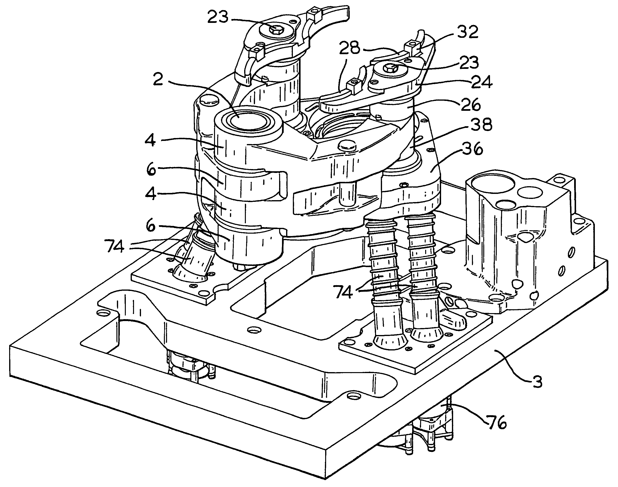
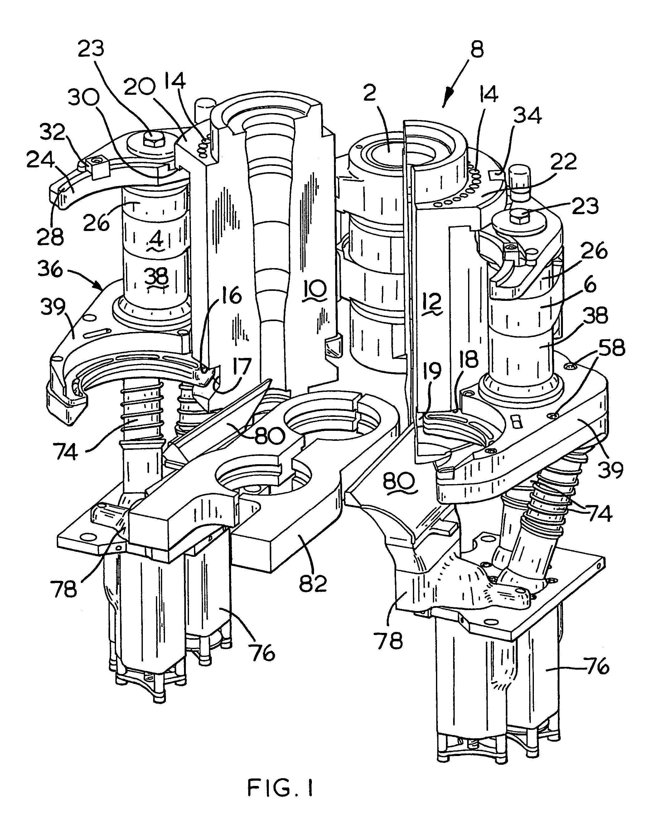
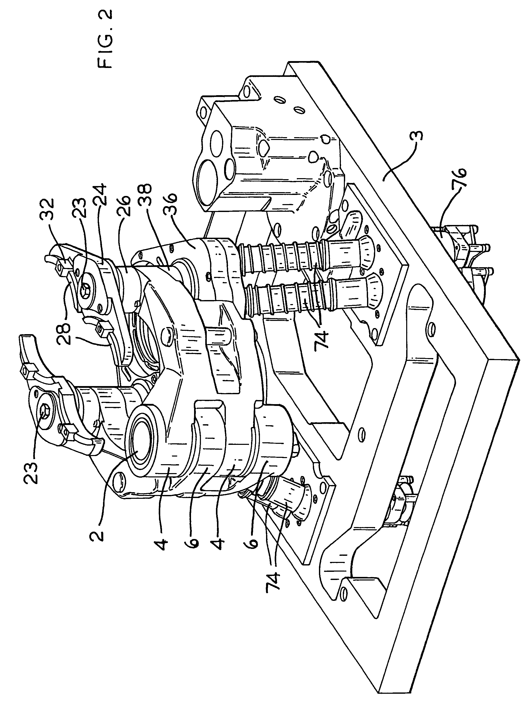
[0013]A multi gob glassware forming machine, specifically a double gob machine comprises a mold mechanism, FIGS. 1 & 2, mounted on a table 3 of the machine at a blank station of the machine. The mold mechanism comprises a pivot 2 fixed in the machine and two mold arms 4,6, mounted on the pivot 2 and adapted to support two blank molds, only one, 8, of which is shown in an open condition in FIG. 1. The blank mold 8 comprises two mold members 10,12, which are generally cylindrical in shape and each of which has straight cooling passages 14 extending axially through the mold member from a lower end face 16,18 to an upper end face 20, 22 of the mold members. It can be seen that the lower end faces 16, 18 bound a recess 17, 19 extending round an outer face of a lower end portion of the mold members, and the cooling passages 14 open into the recesses 17, 19 when the mold members are in position. It will be understood that the mechanism illustrated is adapted to have two blank molds, i.e. f...


PUM

PropertyMeasurementUnit
Volumeaaaaaaaaaa

Abstract

A mold cooling system is disclosed for the blank mold halves of an I.S. machine. The mold halves are supported at their bottom by a lower hanger assembly which includes a discrete plenum for each of the mold halves. Each plenum is isolated and has its own air supply which includes an adjustable flow control. This provides complete control of the mold cooling process.

Description

[0001]This invention relates to a mold mechanism at a blank station of an I.S. type glassware forming machine.BACKGROUND OF THE INVENTION[0002]In the production of glass containers by the press and blow method on the well known I S type machine, a gob of glass is provided to a blank or parison mold comprising two mold members or halves which are supported by a mold mechanism at a blank station of the machine, which mold members can be closed to form a mold cavity_ The glass in the mold cavity is pressed into the required shape of a parison by a plunger moving upwardly into the mold cavity, a lower portion of the glass being forced into a neck ring of the mold. The plunger is then withdrawn and the parison is carried by the neck ring away from the blank station and is transferred to a blow mold station where it is blown to the required shape. In the blow and blow method a gob of glass is provided to the parison mold and is then blown into the required shape of a parison. The shaped p...

Claims


Application Information

Patent Timeline
IPC IPC(8): C03B9/38C03B11/12C03B9/197
CPCC03B9/3875
Inventor MEYER, WILLIMUELLER, THOMAS
Owner EMHART GLASS SA
Why Eureka
Try Eureka