

Back reaming tool
a back reaming tool and tool technology, applied in the direction of shaft sinking, cutting machines, shaft equipment, etc., can solve the problems of limited application, limited conduit diameter, and the need to replace the entire reaming tool,
- Summary
- Abstract
- Description
- Claims
- Application Information
AI Technical Summary
Problems solved by technology
Method used
Image

Examples
Embodiment Construction
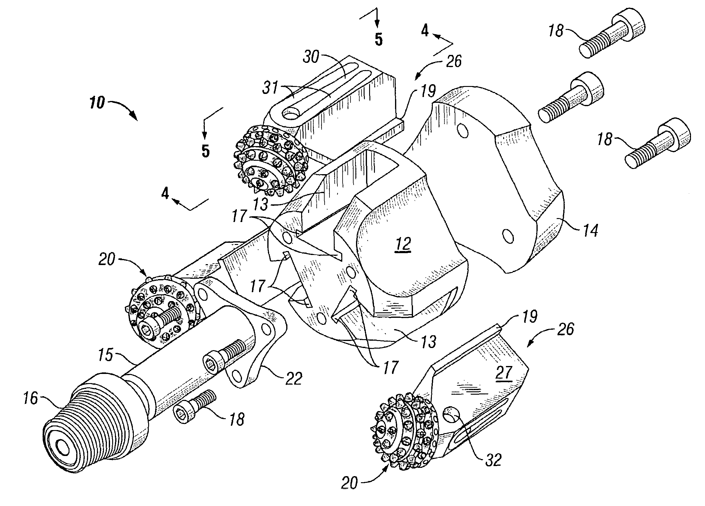
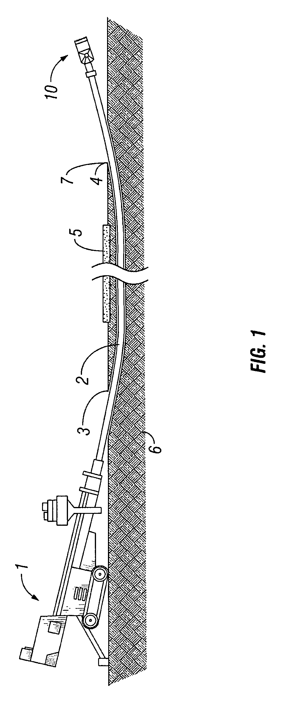
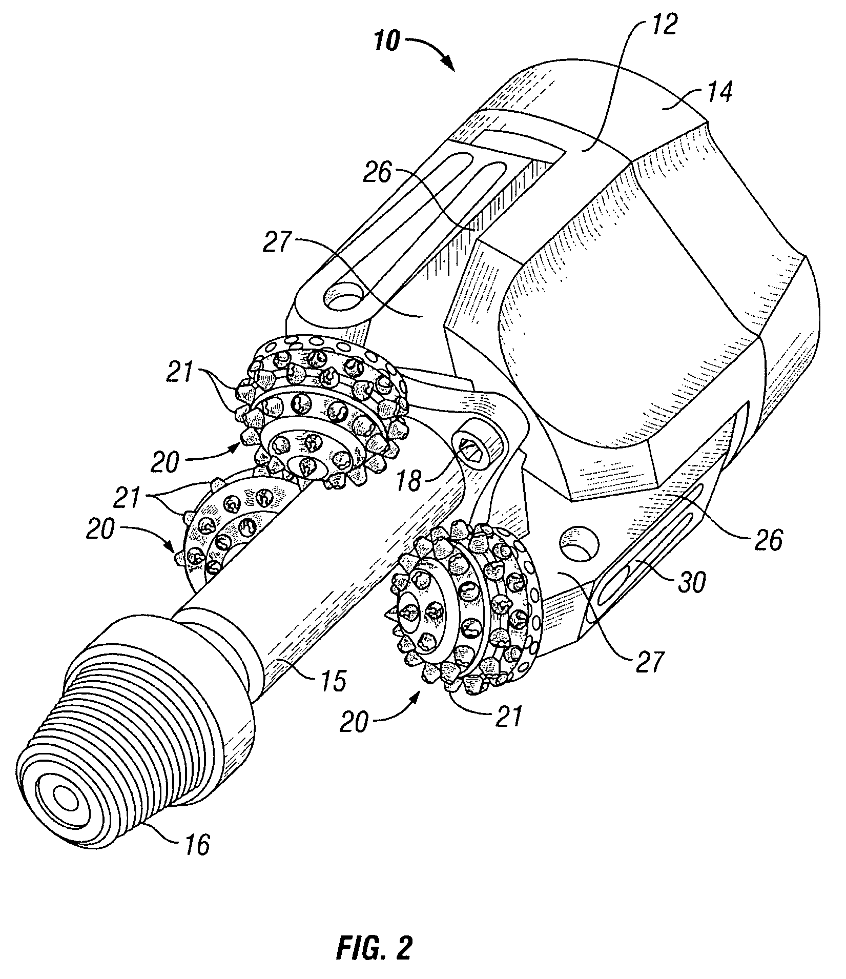
[0026]FIG. 1 shows one embodiment of a back reaming tool 10 used with a horizontal drilling rig 1 to drill a subsurface conduit 7 in earth formations 6 underneath the position of an obstruction 5 at the earth's surface. In this example, the obstruction 5 is a roadway, but it should be clearly understood that the obstruction, and the type of drilling rig used are not intended to limit the invention. Generally speaking, the drilling rig 1 turns threadedly coupled segments of drill pipe 2 while pulling thereon, so that the back reaming tool 10 can enlarge the diameter of the conduit 7 as it traverses the span between an exit hole 4 and an entry hole 3 previously drilled using a conventional drill bit (not shown). The back reaming tool 10 is coupled to the drill pipe 2 generally at the position of the exit hole 4 and is then pulled along the conduit 7 as it is rotated to enlarge the diameter of the conduit 7. In some cases, the back reaming tool 10 can be pushed through a drill hole or ...
PUM
 Abstract
Description
Claims
Application Information