Method and apparatus for protecting surfaces of optical components

a technology of optical components and protective surfaces, applied in the direction of optical radiation measurement, photomechanical equipment, instruments, etc., can solve the problems of unintended localized modification of the light transmission property of the photomask, localized light transmission errors in the substrate or pattern layer, and adversely affecting the operation of the resulting circui

Active Publication Date: 2006-11-21
KLA TENCOR TECH CORP
View PDF23 Cites 139 Cited by
  • Summary
  • Abstract
  • Description
  • Claims
  • Application Information

AI Technical Summary

Problems solved by technology

The presence of defects on the surfaces of the photomasks, reticles, or wafers are highly undesirable and adversely affect the operation of the resulting circuits.
The defects can be due to, but not limited to, a portion of the pattern being absent from an area where it is intended to be present, a portion of the pattern being present in an area where it is not intended to be, chemical deposition or residues from the photomask manufacturing processes which cause an unintended localized modification of the light transmission property of the photomask, artifacts in the photomask substra

Method used


Image

  • Method and apparatus for protecting surfaces of optical components
  • Method and apparatus for protecting surfaces of optical components
  • Method and apparatus for protecting surfaces of optical components

Examples


Embodiment Construction

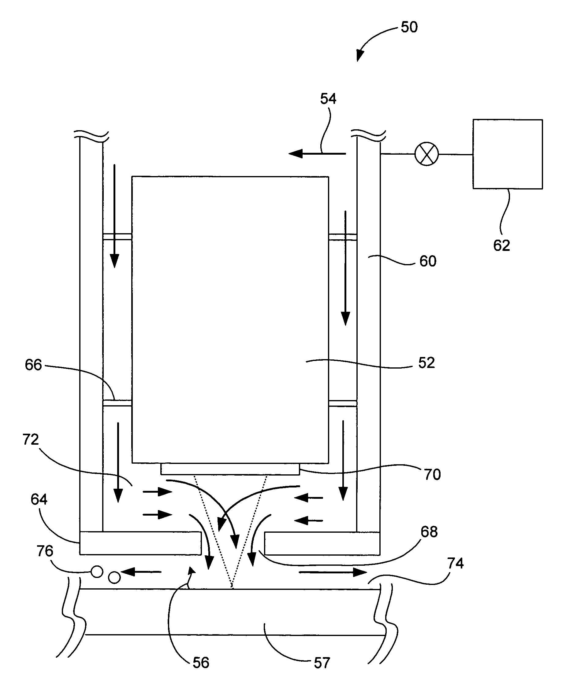
[0031]The invention pertains to mechanisms for protecting surfaces of optical components of an optical inspection system. One aspect of the invention relates to a gas purge system that produces a gas stream that blocks contaminants from reaching the optical surfaces of the optical components and that transports contaminants away from the optical surfaces of the optical components. Another aspect of the invention relates to a transparent cover that physically blocks contaminants from reaching the optical surfaces of the optical components. Yet another aspect of the invention relates to a combination of the gas purge system and the transparent cover.

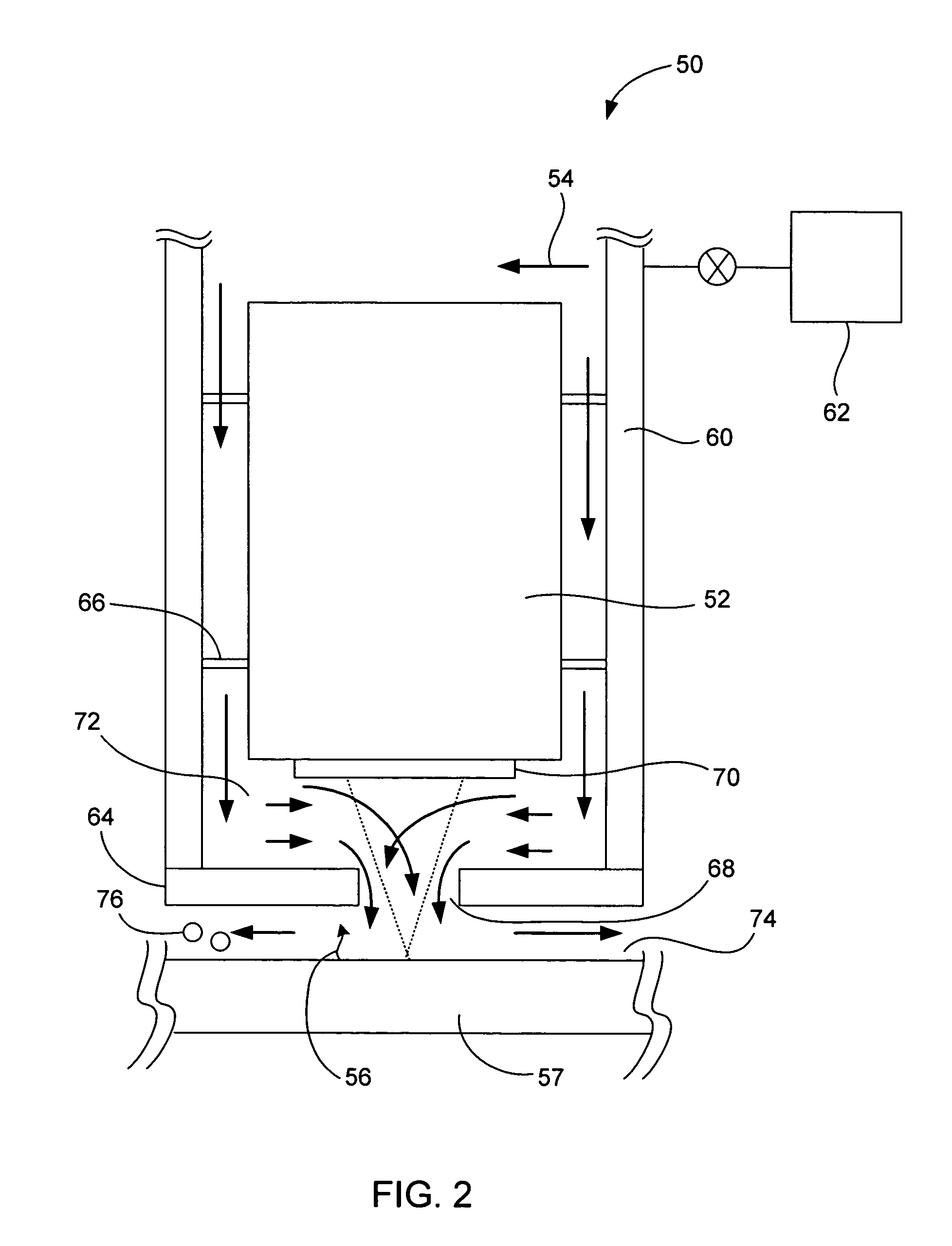
[0032]These and other embodiments of the invention are discussed below with reference to FIGS. 1–15. However, those skilled in the art will readily appreciate that the detailed description given herein with respect to these figures is for explanatory purposes as the invention extends beyond these limited embodiments.

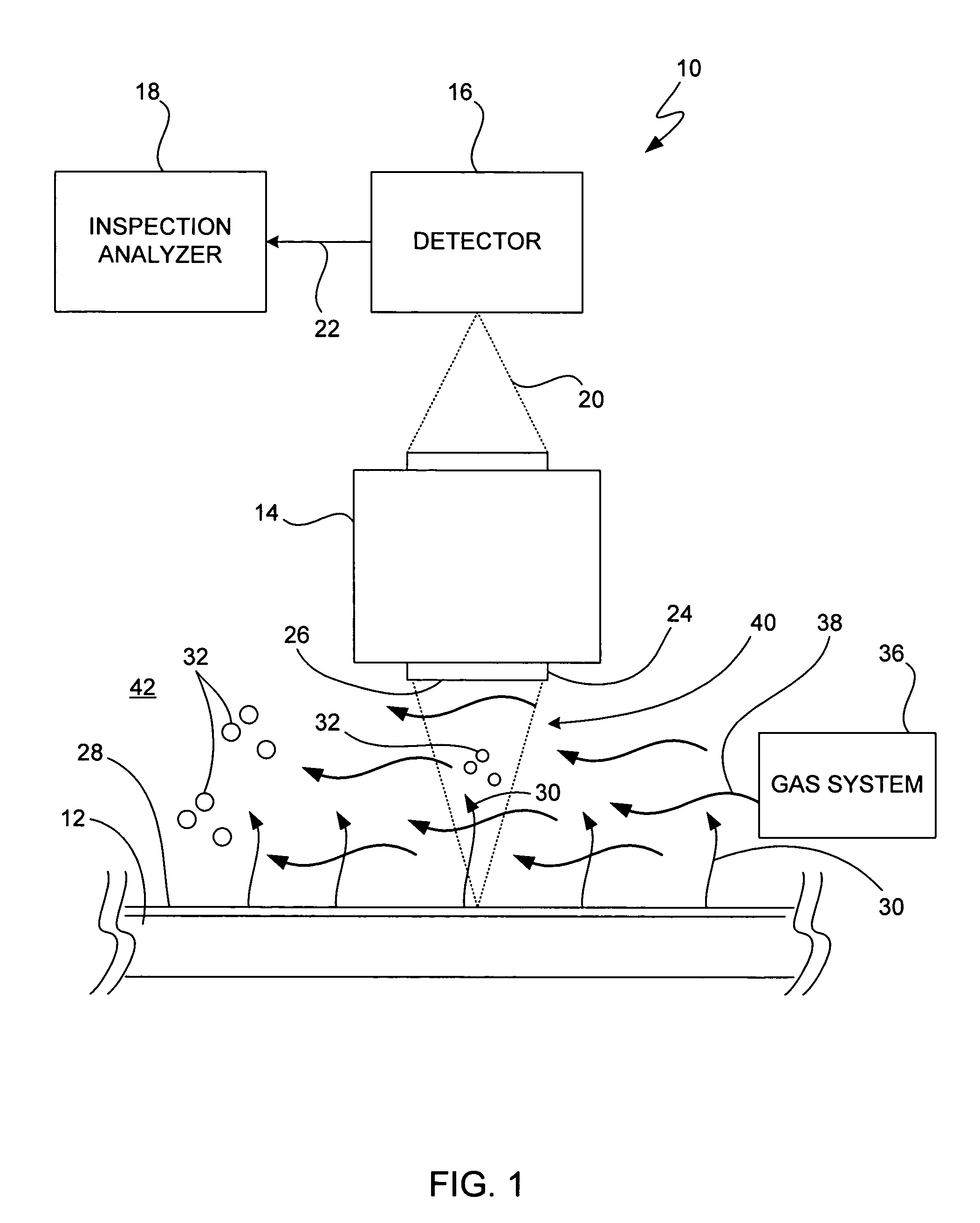
[0033]FIG. 1 is a simpl...


PUM


Abstract

The invention pertains to mechanisms for protecting surfaces of optical components of an optical inspection system. One aspect of the invention relates to a gas purge system that produces a gas stream that blocks contaminants from reaching the optical surfaces of the optical components and that transports contaminants away from the optical surfaces of the optical components. Another aspect of the invention relates to a transparent cover that physically blocks contaminants from reaching the optical surfaces of the optical components. Yet another aspect of the invention relates to a combination of the gas purge system and the transparent cover.

Description

CROSS REFERENCE TO RELATED APPLICATIONS[0001]This application claims the priority of U.S. Patent Application No. 60 / 419,668, filed Oct. 17, 2002, entitled “METHOD AND APPARATUS FOR PROTECTING SURFACES OF OPTICAL COMPONENTS” and which is hereby incorporated herein by reference.FIELD OF THE INVENTION[0002]The present invention relates to optical inspection systems for inspecting a substrate such as reticles, photomasks, wafers and the like. More particularly, the present invention relates to mechanisms for protecting surfaces of optical components of the optical inspection system.BACKGROUND OF THE INVENTION[0003]Integrated circuits are made by photolithographic processes, which use photomasks or reticles and an associated light source to project a circuit image onto a wafer. The presence of defects on the surfaces of the photomasks, reticles, or wafers are highly undesirable and adversely affect the operation of the resulting circuits. The defects can be due to, but not limited to, a ...

Claims


Application Information

Patent Timeline
IPC IPC(8): G01J1/42
CPCG01N21/15G01N21/9501G01N21/956G02B27/0006G03F7/70883G03F7/70908G03F7/70916G01J2001/0276G01N2021/151
Inventor DELGADO, GILMCMURTRY, JOHNWILEY, JAMES
Owner KLA TENCOR TECH CORP
Why Eureka
Try Eureka