Sealing ring for an intake manifold
- Summary
- Abstract
- Description
- Claims
- Application Information
AI Technical Summary
Benefits of technology
Problems solved by technology
Method used
Image

Examples
Embodiment Construction
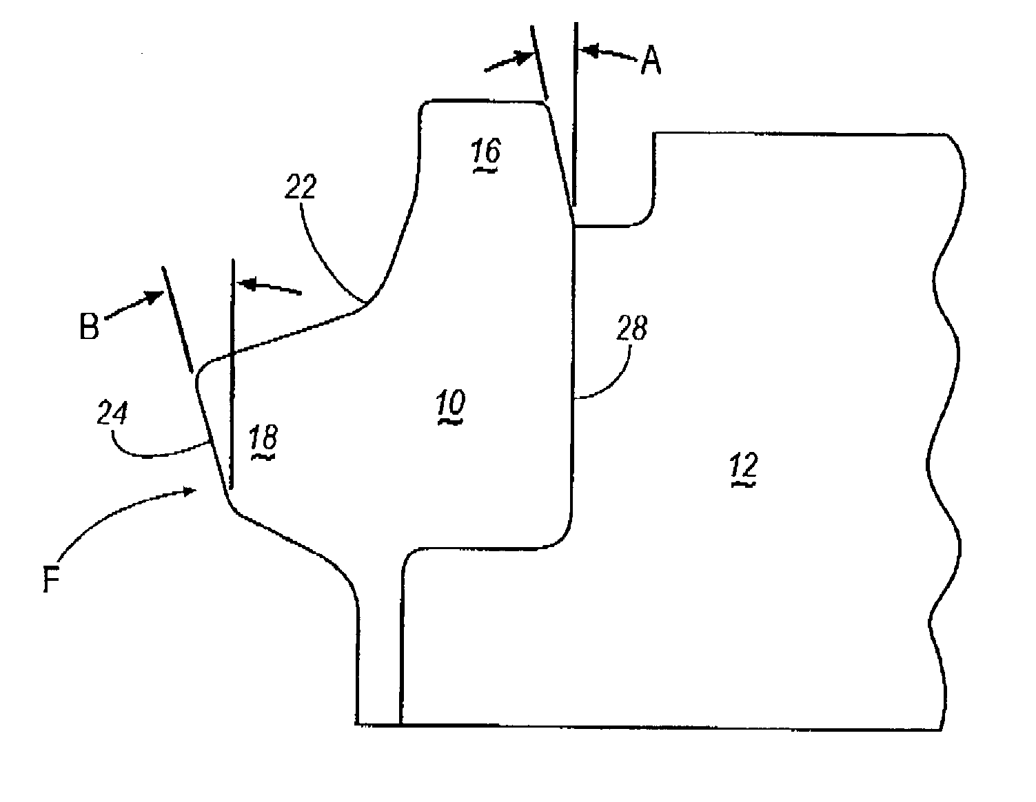
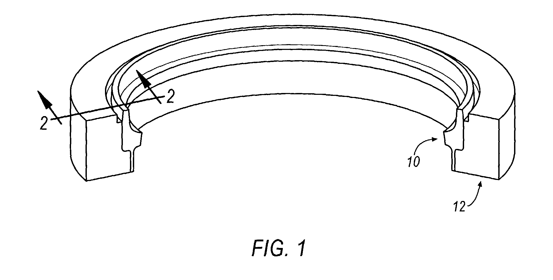
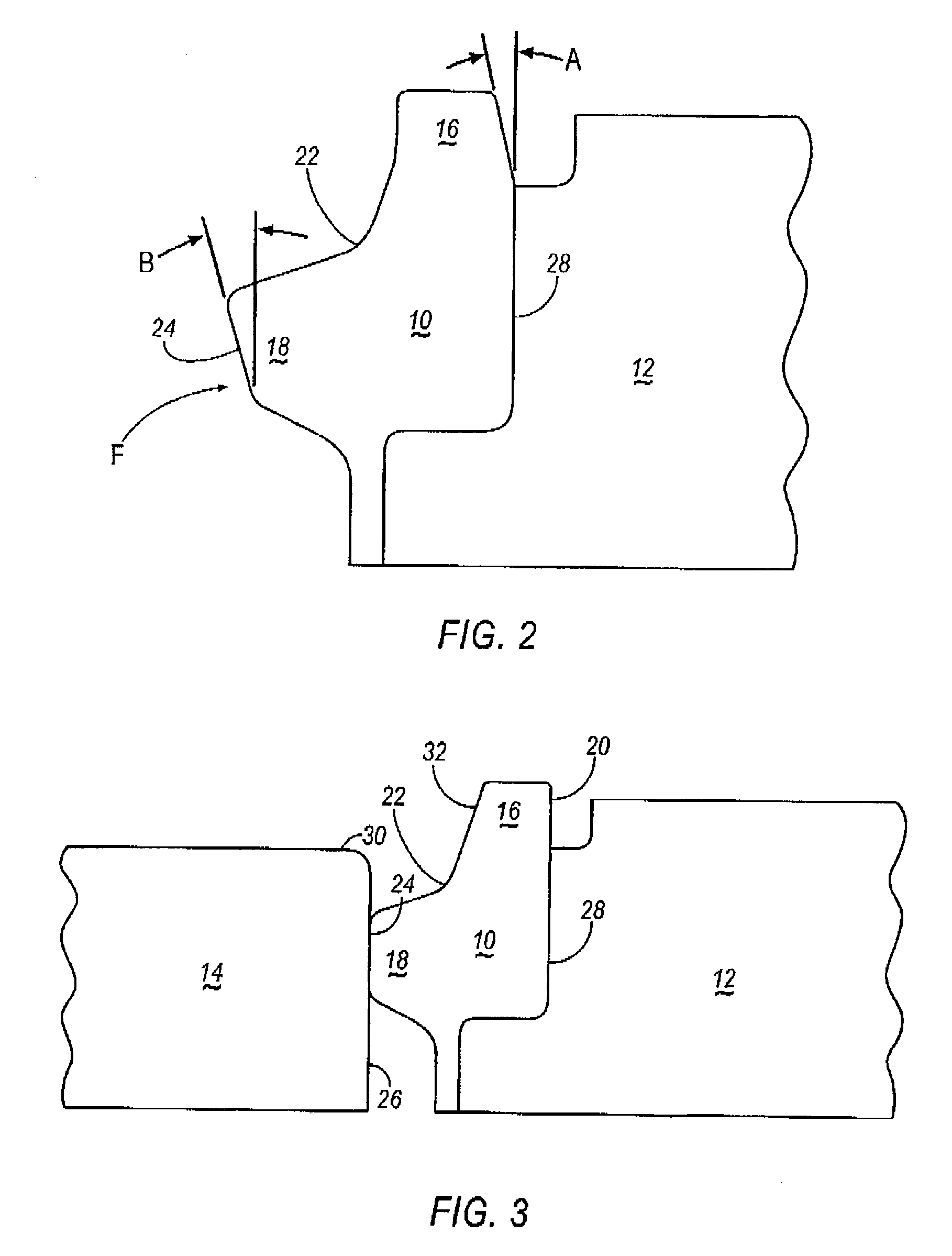
[0008]Referring to FIGS. 1–3, a sealing ring 10, is illustrated according to one embodiment of the present invention. The sealing ring 10 is positioned between the cylinder head 12 of an internal combustion engine (not shown) and the intake pipe 14 of an intake manifold (not shown). FIGS. 1–3 illustrate one intake pipe 14, however, it can be appreciated that the present invention is not limited by the number of intake pipes 14 or the arrangement of the intake pipes 14 within the intake manifold, and may be practiced with any number and arrangement of intake pipes 14.
[0009]The sealing ring 10 has a generally annular body that includes a top bead 16 and a side bead 18 and is preferably made of an elastomeric material. The top bead 16 has an outer surface 20 and an inner surface 32. Side bead 18 has an inner surface 24. The top bead 16 and the side bead 18 form a generally reverse L-shape, as best seen in FIG. 2. Top bead 16 and side bead 18 are integrally connected together by a radiu...
PUM
 Abstract
Description
Claims
Application Information
 - Generate Ideas
- Intellectual Property
- Life Sciences
- Materials
- Tech Scout
- Unparalleled Data Quality
- Higher Quality Content
- 60% Fewer Hallucinations
Browse by: Latest US Patents, China's latest patents, Technical Efficacy Thesaurus, Application Domain, Technology Topic, Popular Technical Reports.
© 2025 PatSnap. All rights reserved.Legal|Privacy policy|Modern Slavery Act Transparency Statement|Sitemap|About US| Contact US: help@patsnap.com