Triple purpose lay-up tool

a three-purpose, tool technology, applied in the direction of manufacturing tools, dough shaping, buttons, etc., can solve the problems of high composite part reject and rework rate, relative cost, inaccuracy and inconsistency,

Active Publication Date: 2006-11-28
THE BOEING CO
View PDF7 Cites 37 Cited by
  • Summary
  • Abstract
  • Description
  • Claims
  • Application Information

AI Technical Summary

Problems solved by technology

However, despite the recognized benefits of this type of parts and their wide use, they are relatively expensive, in part because the manufacturing processes for producing these parts remain clumsy and difficult to use, contributing high reject and rework rates for composite parts.
The tool locating and the hand mounting result in in

Method used


Image

  • Triple purpose lay-up tool
  • Triple purpose lay-up tool
  • Triple purpose lay-up tool

Examples


Embodiment Construction

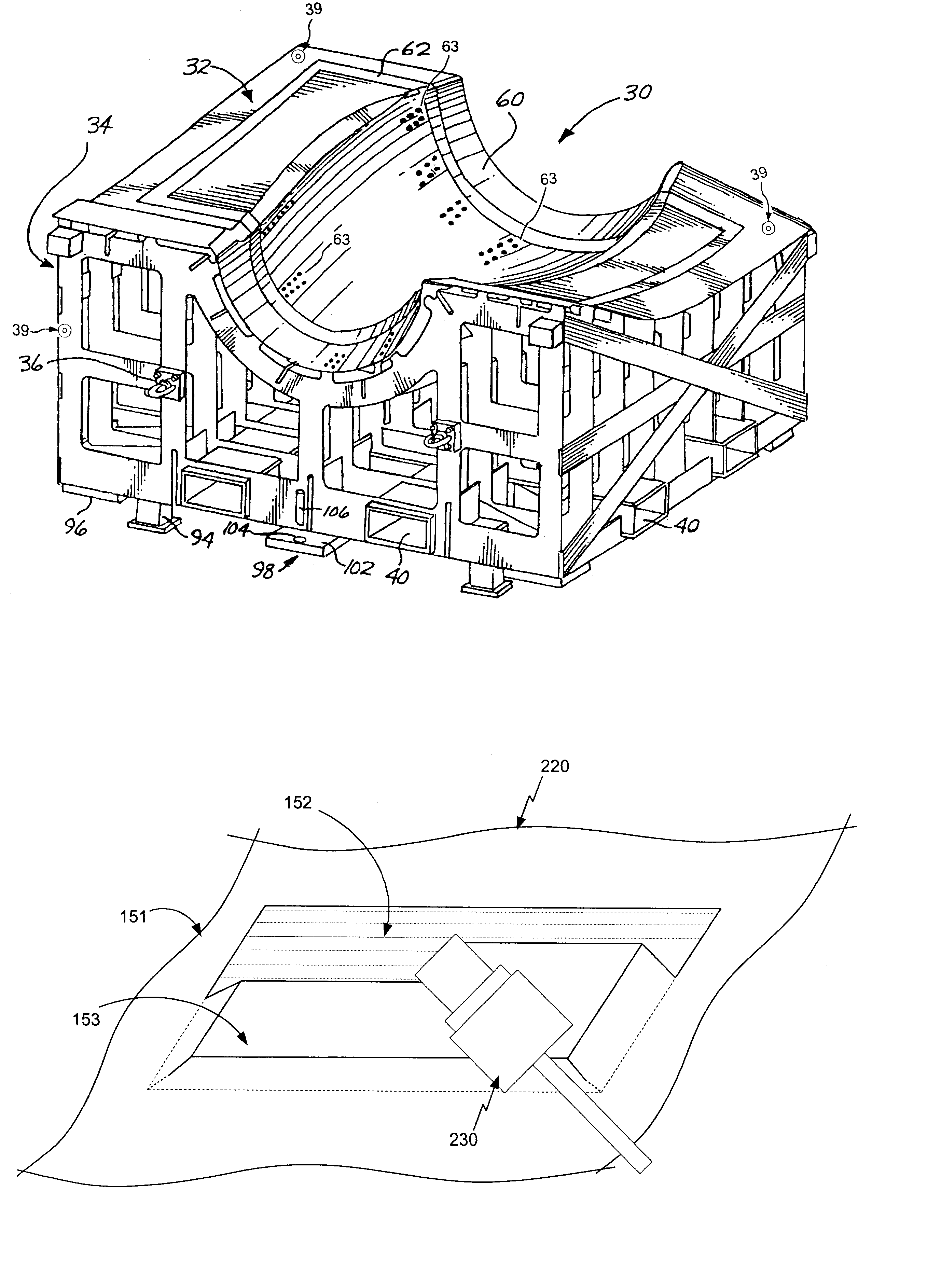
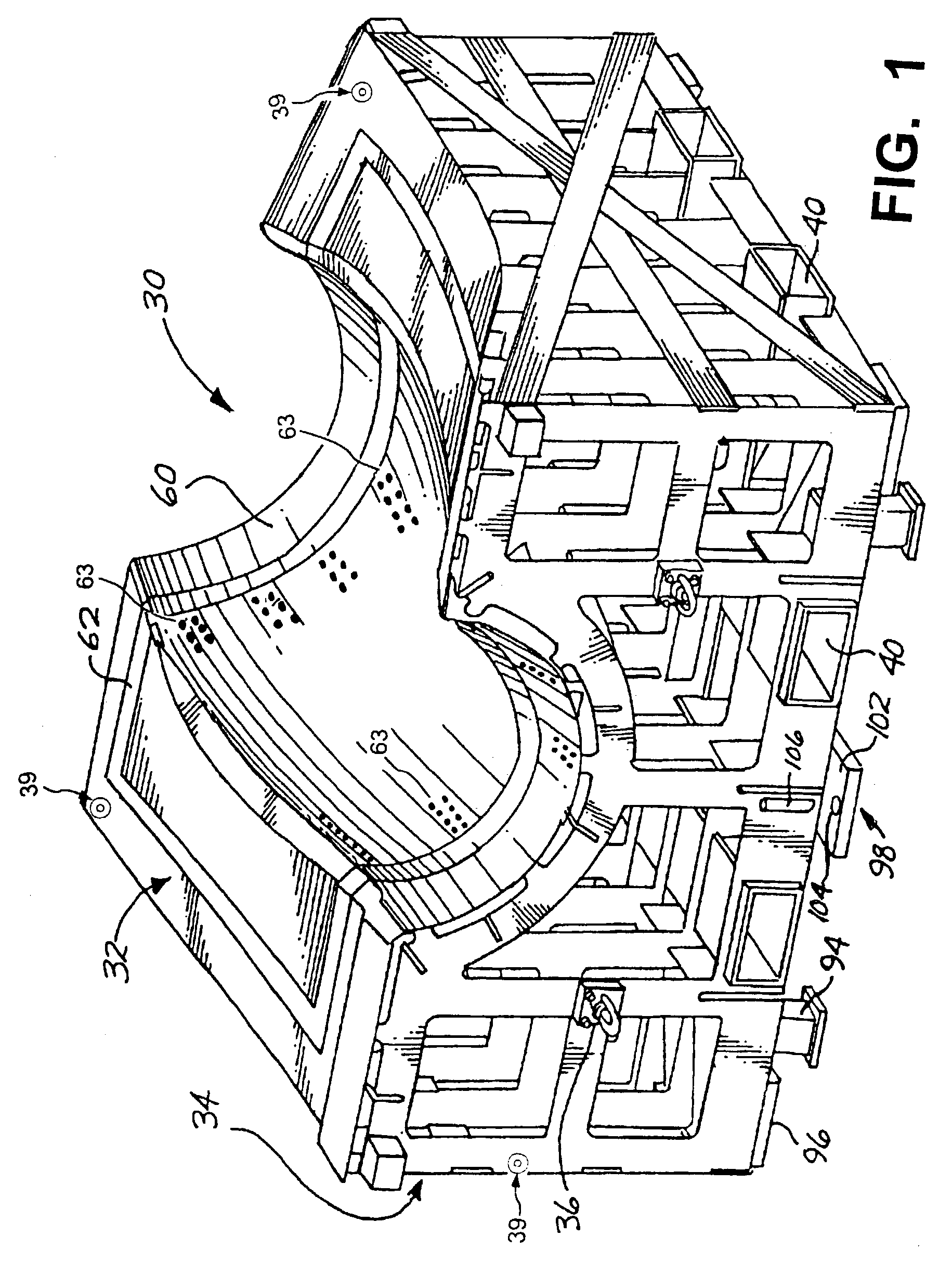
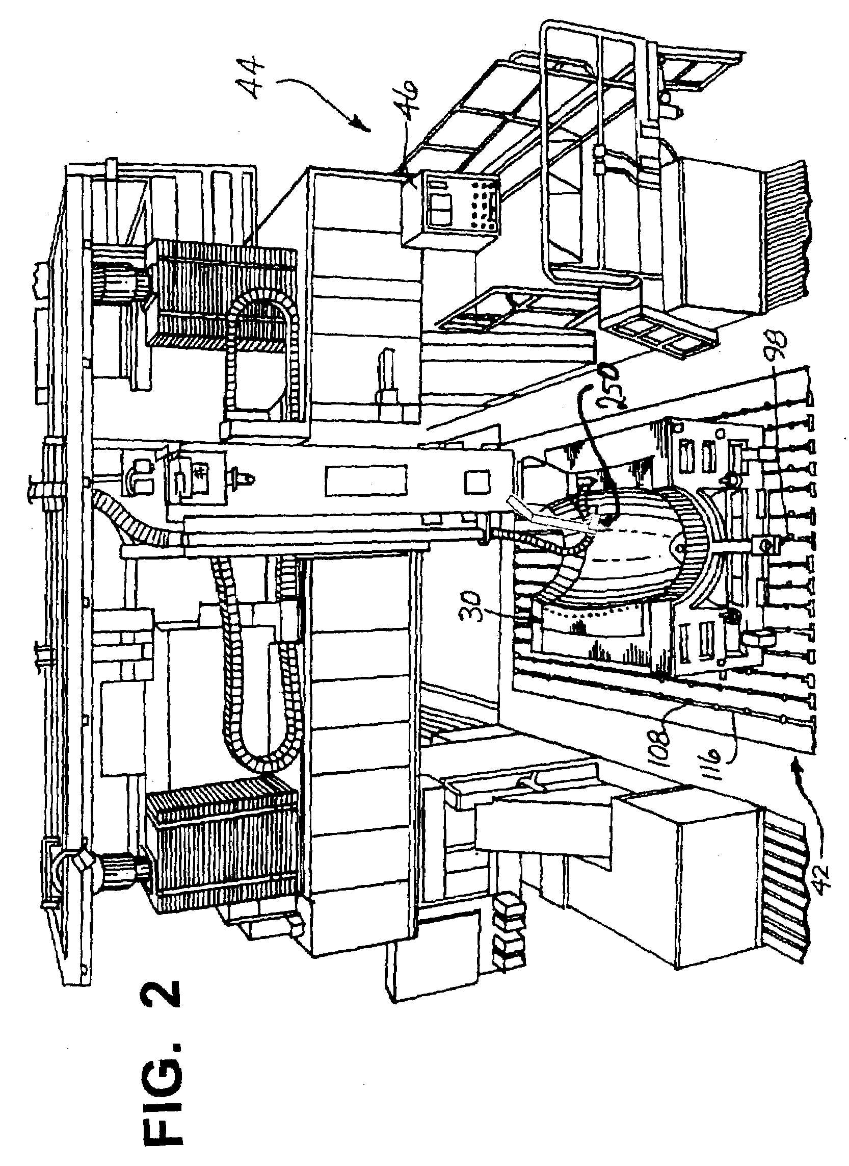
[0026]The present invention provides a method and apparatus for use in forming, constructing and / or assembling a composite part. The present invention allows a composite part to be formed, machined, tooled, hardware to be positioned and machined with the composite part, and sculpting of the composite part all in a single apparatus. The method and apparatus can be used to manufacture and construct composite parts for any number of industries, including aerospace, automotive, manufacturing and other industries. The present invention greatly improves accuracy and consistency of the manufacturing, constructing and assembling of the composite component, simplifies the positioning and tooling of the hardware, and achieves this in a reduced time and at reduced costs.

[0027]The composite part or component formed, tooled and assembled can be substantially any part. For example, the part can be a component of an airplane manufactured to specific guidelines and tolerances. Similarly, the compos...


PUM

PropertyMeasurementUnit
Sizeaaaaaaaaaa
Depthaaaaaaaaaa

Abstract

The present invention provides a method and apparatus for use in manufacturing a composite part includes molding a composite part on a lay-up tool, machining a sacrificial portion of a first surface for securing a first hardware device with the composite part while the part is on the lay-up tool and cutting the part forming a peripheral edge while the part is on the lay-up tool. The method can further include positioning the first hardware device in contact with a machined interface of the composite part and machining the part including drilling a plurality of positioning holes through the hardware device and the part while the part is on the lay-up tool. The machining can include machining the sacrificial portion creating a machined interface and positioning the hardware device on the machined interface.

Description

[0001]The present invention relates generally to the manufacturing and construction of composite parts, and more particularly to lay-up tools on which composite parts are sculpted, bonded and tooled, and on which hardware is aligned and mounted to the composite part without removing the part from the lay-up tool.BACKGROUND OF THE INVENTION[0002]Composite parts have become commonly used throughout industry because of their engineering qualities and low weight. However, despite the recognized benefits of this type of parts and their wide use, they are relatively expensive, in part because the manufacturing processes for producing these parts remain clumsy and difficult to use, contributing high reject and rework rates for composite parts.[0003]Previous processes for making composite parts require the construction and / or formation of the part in a bond assembly jig (BAJ). If the part has a core, the core is applied on the BAJ. Once the core is bonded onto the part, the part is removed ...

Claims


Application Information

Patent Timeline
IPC IPC(8): B29C70/30B29C70/54
CPCB29C70/545
Inventor ENGWALL, DWIGHT L.COSTELLO, JOHN F.
Owner THE BOEING CO
Why Eureka
Try Eureka