Optical scanner and image forming apparatus

an image forming apparatus and optical scanner technology, applied in the field of optical scanners and image forming apparatuses, can solve the problems of increasing apparatus costs, limiting image formation speed, and increasing the probability of malfunctions

Active Publication Date: 2006-12-05
RICOH KK
View PDF29 Cites 57 Cited by
  • Summary
  • Abstract
  • Description
  • Claims
  • Application Information

AI Technical Summary

Problems solved by technology

In the tandem type image forming apparatus, a larger number of light sources are utilized and consequently the number of components for the apparatus is increased, and this results in a cost increase for the apparatus.
In the image forming apparatus, failure of light sources can be cited as the main cause for malfunctions of units that perform optical scanning, and as the number of light sources is increased, a probability of malfunctions becomes higher.
However, in an embodiment specifically described in the patent application, there is a limitation to speeding-up of image formation because single optical scanning on two photoconductors is performed with the light beams from one light source by one rotation of a optical deflector.

Method used


Image

  • Optical scanner and image forming apparatus
  • Optical scanner and image forming apparatus
  • Optical scanner and image forming apparatus

Examples


Embodiment Construction

[0027]Exemplary embodiments of the present invention are explained in detail below with reference to the accompanying drawings.

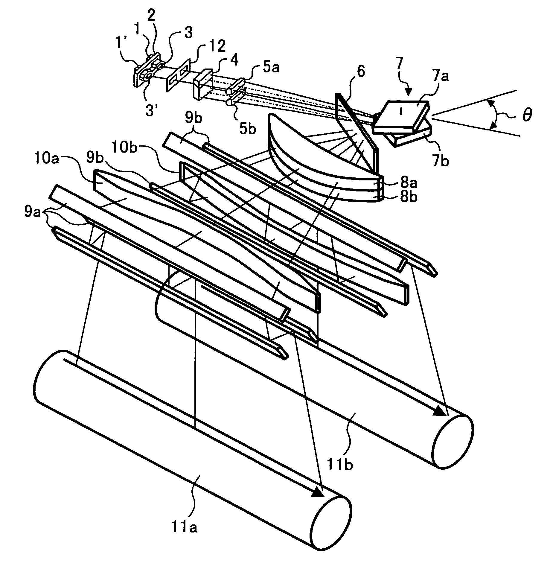
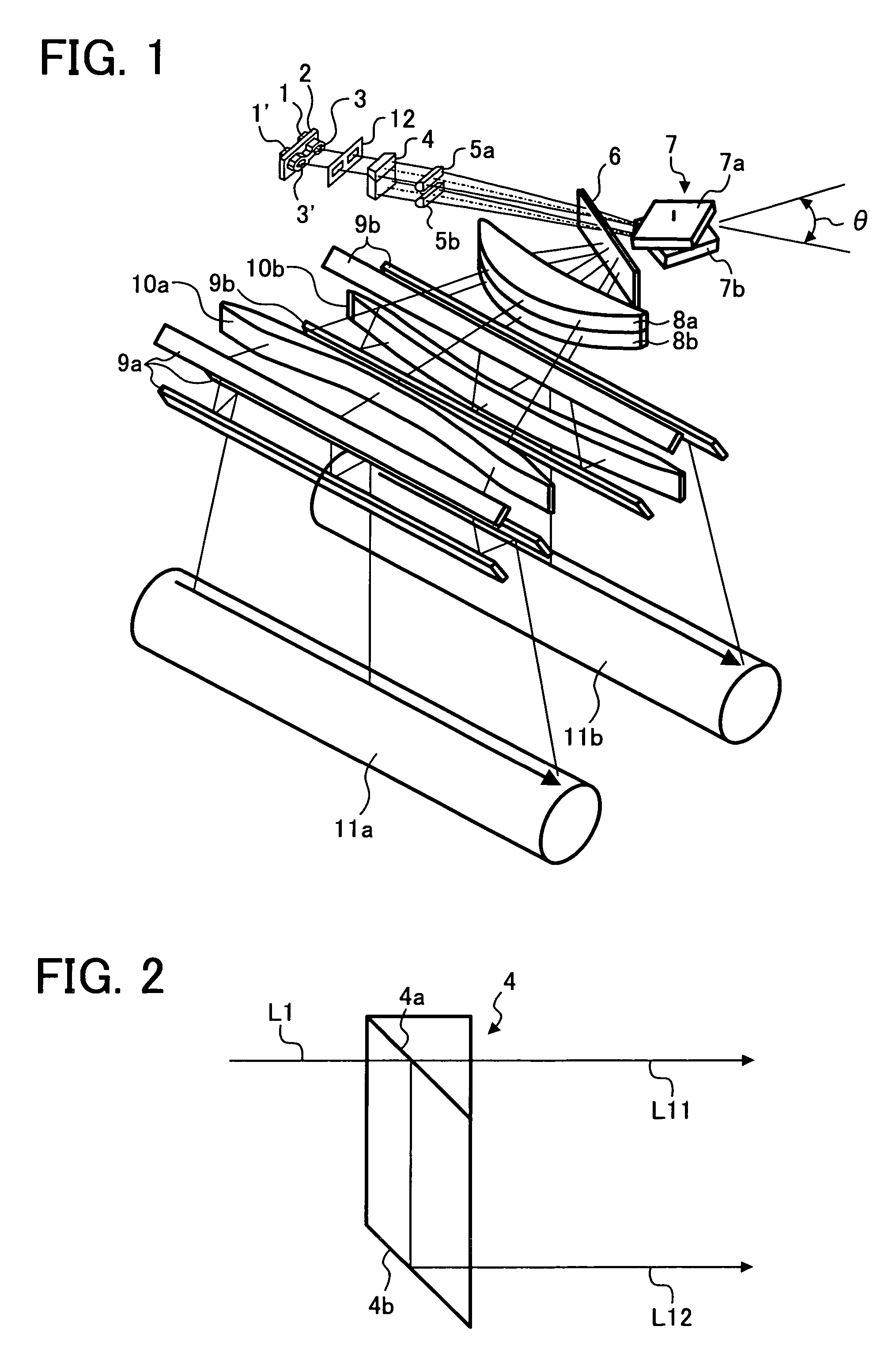
[0028]FIG. 1 is a view for explaining an embodiment of the optical scanner according to the invention. In FIG. 1, reference signs 1 and 1′ represent semiconductor lasers. The semiconductor lasers 1 and 1′ are two light-emission sources constituting one light source, and each of the semiconductor lasers emits one light beam. The semiconductor lasers 1 and 1′ are held in a predetermined positional relationship by a holder 2.

[0029]Each of the light beams emitted from the semiconductor lasers 1 and 1′ is converted into a luminous flux form (parallel luminous flux or luminous flux with weak divergence or with weak convergence) suitable for subsequent optical systems by coupling lenses 3 and 3′. In this example, the light beams coupled by the coupling lenses 3 and 3′ are parallel luminous flux.

[0030]Each light beam outgoing from the coupling lens to become a desir...


PUM


Abstract

A scanner which optically scans n positions, where n≧2, has m light sources which emits p beams, where 1≦m<n and p≦1; a unit which splits each beam into q beams in a sub-scanning direction and forms each beam into a predetermined form, where 2≦q≦n; a deflector having a plurality of planes around a rotation axis and configured to deflect a number of beams equal to (q·m·p) from the m sources which are incident on the deflector; n optical systems which guide n sets of beams deflected to corresponding positions to form light spots; and a selecting unit which selects a path for each of the n sets of beams, wherein the deflector is at least a part of the selecting unit.

Description

CROSS-REFERENCE TO RELATED APPLICATIONS[0001]The present document incorporates by reference the entire contents of Japanese priority document, 2003-328941 filed in Japan on Sep. 19, 2003.BACKGROUND OF THE INVENTION[0002]1) Field of the Invention[0003]The present invention relates to an optical scanner and an image forming apparatus, and particularly to an optical scanner and an image forming apparatus that are utilized for optical printer, digital copying machine, plain-paper facsimile, and the like.[0004]2) Description of the Related Art[0005]In an image forming apparatus utilizing an electrophotographic process used in optical printer, digital copying machine, plain-paper facsimile, and the like, the colorization and faster printing have become common, and a tandem type image forming apparatus using a plurality of photoconductors is becoming widespread. In the tandem type image forming apparatus, a larger number of light sources are utilized and consequently the number of componen...

Claims


Application Information

Patent Timeline
Patent Type & Authority Patents(United States)
IPC IPC(8): G02B26/08B41J2/44B41J2/47G02B13/00G02B17/08G02B26/10G02B26/12H04N1/036H04N1/113
CPCB41J2/473G02B26/123
Inventor HAYASHI, YOSHINORI
Owner RICOH KK
Why Eureka
Try Eureka