
Visible light space division multiple access multichannel communication system

A technology of space division multiple access and multi-channel communication, which is applied in transmission system, electromagnetic wave transmission system, free space transmission, etc.

Inactive Publication Date: 2008-07-30
EAST CHINA UNIV OF SCI & TECH
View PDF1 Cites 61 Cited by
  • Summary
  • Abstract
  • Description
  • Claims
  • Application Information

AI Technical Summary

Problems solved by technology

This patent is only aimed at the receiving terminal, and does not involve the relationship between the optical system and the required optical system when using the area array image sensor to receive optical signals, how to select the detection unit on the image sensor, how to perform subsequent signal processing and other key technical issues, nor Multiple-path and multiple-access issues involving transmitted and received signals

Method used


Image

  • Visible light space division multiple access multichannel communication system
  • Visible light space division multiple access multichannel communication system
  • Visible light space division multiple access multichannel communication system

Examples


Embodiment Construction

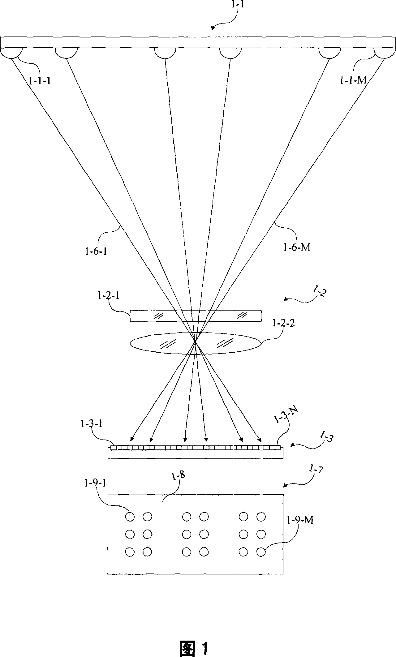
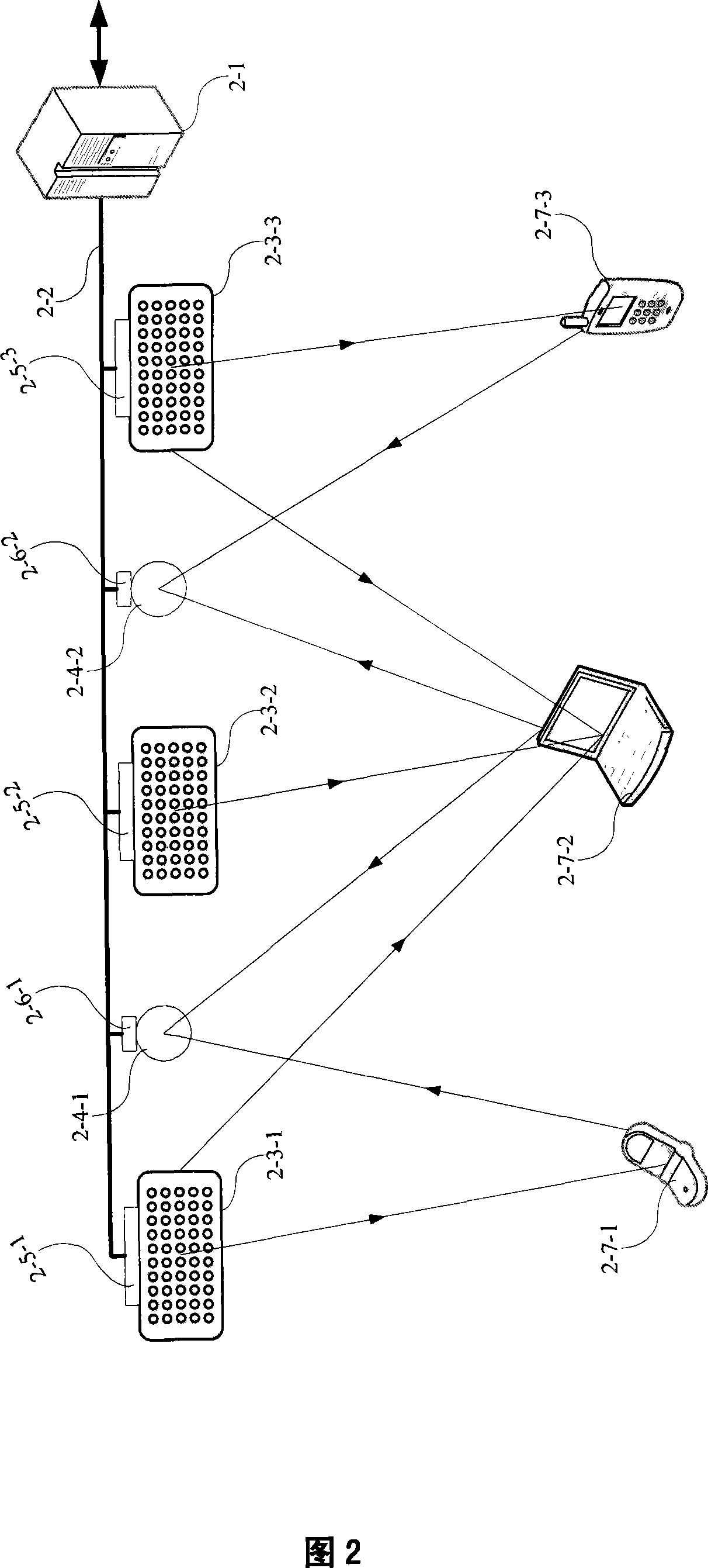
[0028] A specific embodiment of the present invention is an indoor communication network, as shown in FIG. 2 , which includes a visible light access point device placed on the roof and three network nodes with optical transceiver functions. The optical access point consists of access server or gateway 2-1, transmission cable 2-2, LED light sending array 2-3-1 / 2 / 3 and its controller 2-5-1 / 2 / 3, light receiving Unit 2-4-1 / 2 and its controller 2-6-1 / 2. The network nodes are three portable terminal devices 2-7-1 / 2 / 3. The terminal equipment 2-7-1 / 2 / 3 uses light as a communication medium to access the server through an optical access point or the gateway 2-1 to connect to an external network. Such a network may be the Internet or a private network.

[0029] Figure 1 shows how terminals within the coverage of the same access point implement visible light space division multiple access communication. Suppose 1-1 is an LED light-emitting array placed on the top of the room. It has M L...


PUM


Abstract

The invention relates to a realization proposal of a visible light space division multi-access multi-channel communication system. A visible light LED array at a sending end sends multiple channels of coded light signals, a light receiver forms the space separated LED image spots on a planar array photodetector by an imaging optical system thereof, the different receivers select their own outputs according to the different positions of image spots and the different response signals of the image elements which are covered by the image spots, thus realizing the tracking of light spots during the space diversity and the movement.

Description

technical field [0001] The invention belongs to the field of optical wireless communication, and is a method for realizing multi-address multi-channel communication between a distributed or array visible light LED lighting system and a fixed or portable device with a photodetector array. Background technique [0002] Visible light LEDs have been widely used in large outdoor advertising screens, indoor information release screens, traffic lights, car lights, lighting and other fields. Driven by the current energy-saving and environmental protection requirements, LED semiconductor lighting will gradually replace incandescent and fluorescent lamps and enter practical applications due to its high brightness, high reliability, low power consumption and long life, and will be popularized in a wide range, especially in offices. Buildings, residences and intelligent transportation fields. According to this development and the current information society's demand for high-speed tran...

Claims


Application Information

Patent Timeline
Patent Type & Authority Applications(China)
IPC IPC(8): H04B10/00H04B10/10H04B10/11
Inventor 樊凌涛
Owner EAST CHINA UNIV OF SCI & TECH
Learn More