Optical scanner and imaging apparatus using the same

a scanning machine and optical scanner technology, applied in the direction of electrographic process equipment, instruments, printing, etc., can solve the problems of unavoidable curving of scanning lines, difficult to realize perfect constant velocity characteristics of optical scanning, and curved scanning lines, so as to improve optical scanning, effective correction of scanning line curving, and good optical scanning

Inactive Publication Date: 2005-06-14
RICOH KK
View PDF6 Cites 64 Cited by
  • Summary
  • Abstract
  • Description
  • Claims
  • Application Information

AI Technical Summary

Benefits of technology

[0022]A more specific object of the present invention is to provide an optical scanner that effectively corrects scanning line curving so that good optical scanning can be performed.
[0023]Another more specific object of the present invention is to pr

Problems solved by technology

It is not easy, however, to realize a perfect constant velocity characteristic of optical scanning due to other characteristics required of the scanning and imaging optical system.
As it is, however, it is common that the scanning line is curved due to processing or assembly error.
In the case of forming the scanning and imaging optical system as a lens system, scanning line curving is unavoidable in multi-beam scanning where the scanning surface is optically scanned by a plurality of light spots separated in the sub scanning direction.
However, the image is better with less distortion even if the distortion is visually unrecognizable.
Even in a monochrome image, however, scanning line curving becomes an unignorable problem if image linearity is considered important as in the case of a CAD (computer-aided design) output because even a slight curve of the scanning line s

Method used


Image

  • Optical scanner and imaging apparatus using the same
  • Optical scanner and imaging apparatus using the same
  • Optical scanner and imaging apparatus using the same

Examples


first embodiment

[0064][First Embodiment]

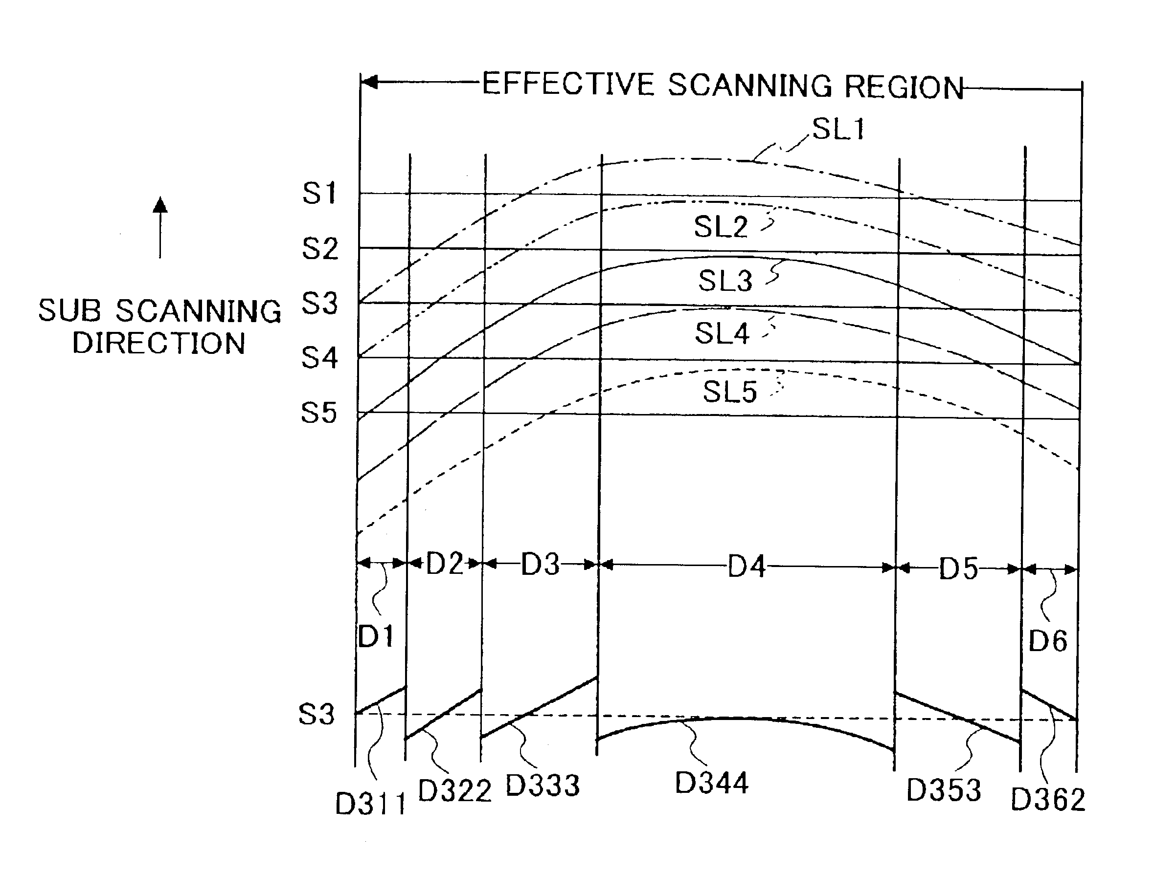
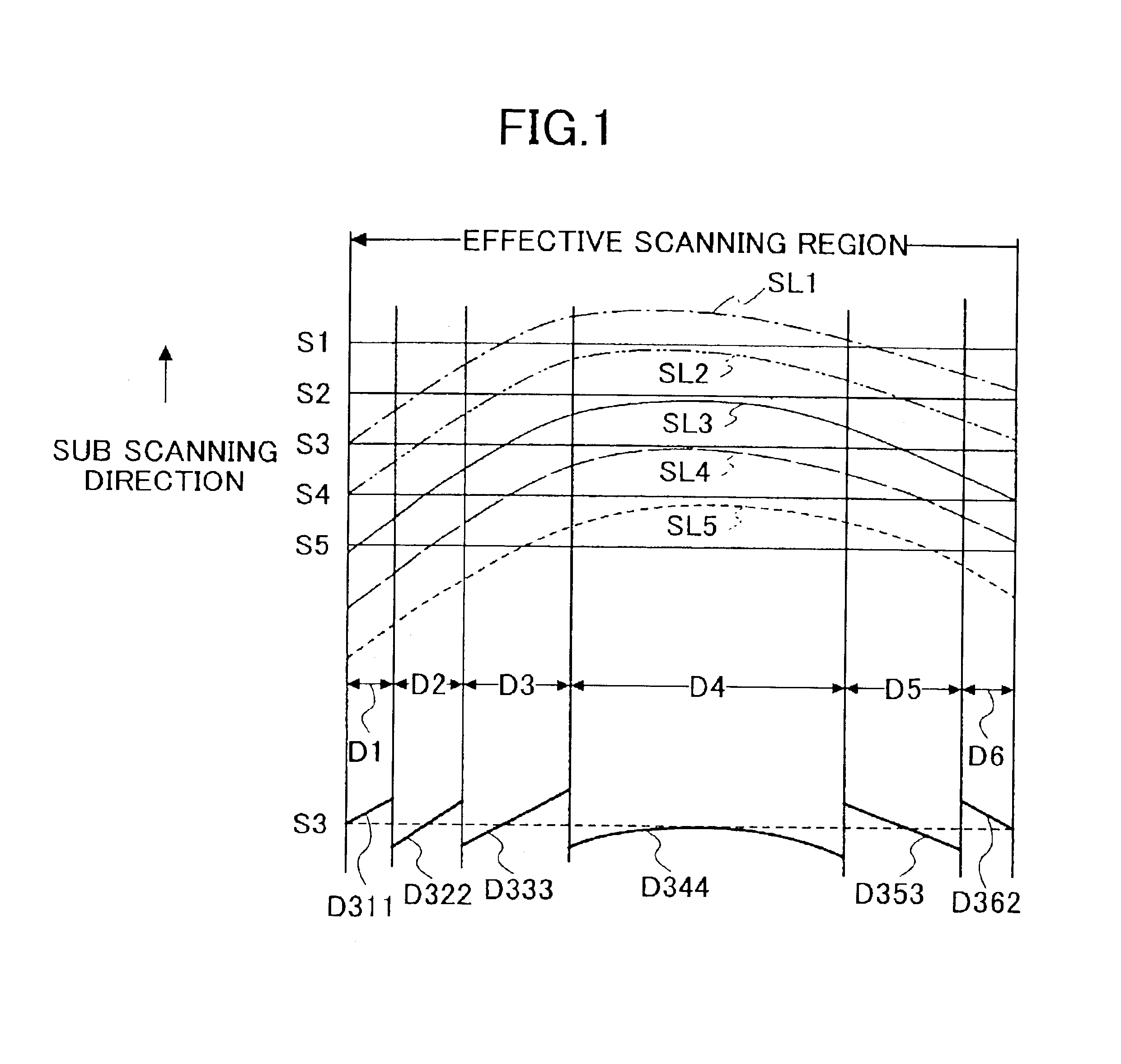
[0065]FIG. 1 is a diagram for illustrating a divided writing method according to the present invention. According to the divided writing method, when one light spot performs optical scanning moving on a scanning surface, in each predetermined part of a scanning line, which is the trace of movement of the light spot, image data for the image line (corresponding to an ideal straight scanning line) closest to the predetermined part is written. That is, every time a light spot optically scans a scanning surface, image data for a plurality of image lines are selected. Thus, each of the image lines is partially written by each optical scan. Accordingly, the image data of each entire image line are written by a plurality of optical scans by the light spot. According to this method, image data for a plurality of image lines are divided and written during a single optical scan by a light spot. Further, image data forming one image line is written by a plurality of opt...

second embodiment

[0180][Second Embodiment]

[0181]A description will be given of a second embodiment of the present invention.

[0182]FIG. 10 is a diagram for illustrating an optical scanner according to the second embodiment of the present invention. FIG. 10 is similar in format to FIG. 1. In FIG. 10, reference numerals S1 through S5 denote five successive image lines as in FIG. 1. The difference between FIGS. 1 and 10 lies in that the five scanning lines SL1 through SL5 of FIG. 1 are drawn by as many optical scans successively performed by a single light spot while the four scanning lines SL1 through SL4 of FIG. 10 are simultaneously drawn by as many light spots. That is, according to the second embodiment of the present invention, the scanning surface is scanned line-sequentially by multi-beam scanning with four light spots. The scanning lines SL1 through SL4 have substantially the same scanning line curving characteristic.

[0183]That is, according to the optical scanner of the second embodiment of th...

third embodiment

[0189][Third Embodiment]

[0190]FIG. 11 is a diagram showing an imaging apparatus according to a third embodiment of the present invention.

[0191]The imaging apparatus of FIG. 11 forms a color image by employing photoconductive photosensitive bodies as photosensitive media. According to the imaging apparatus, component images of four colors of magenta, cyan, yellow, and black are formed to be superimposed on a sheet-like recording medium. Thereby, the color image is obtained.

[0192]The imaging apparatus includes polygon mirrors 151 and 152 having the same shape. The polygon mirrors 151 and 152 are fixed to a common shaft so as to rotate together with the shaft as a single unit. The polygon mirrors 151 and 152, together with a driving part (not shown in the drawing), form an optical deflection and scanning part.

[0193]The imaging apparatus further includes four light source devices, which are not graphically represented in FIG. 11. Light beams emitted from two of the light source devices ...


PUM


Abstract

An optical scanner includes a light source modulated based on image data, an optical deflection and scanning part deflecting a light beam emitted from the light source, and a scanning and imaging optical system condensing the deflected light beam toward a scanning surface so as to form a light spot optically scanning the scanning surface. The effective scanning region of the scanning surface is divided into a plurality of regions according to a scanning line curving characteristic. Suitable image data for optically scanning the divided regions are selected from image data of a plurality of image lines every time the light spot optically scans the effective scanning region, so that the image data of each of the image lines is written with scanning line curving being corrected.

Description

BACKGROUND OF THE INVENTION[0001]1. Field of the Invention[0002]The present invention generally relates to optical scanners and imaging apparatuses, and more particularly to an optical scanner that forms a light spot on a scanning surface by using optical deflection and scanning means and a scanning and imaging optical system and optically scans the scanning surface with the light spot, and an imaging apparatus using such an optical scanner.[0003]2. Description of the Related Art[0004]Optical scanners that deflect a light beam emitted from a light source modulated based on image data in a main (primary) scanning direction using optical deflection and scanning means such as a rotary polygonal mirror, focus the deflected light beam into a light spot on a scanning surface (surface to be scanned) using a scanning and imaging optical system such as an fθ lens, and scan the scanning surface with the light spot formed thereon are widely known in relation to imaging apparatuses such as opti...

Claims


Application Information

Patent Timeline
IPC IPC(8): G02B26/12B41J2/44G02B13/00G02B26/10G03G15/01G03G15/04H04N1/036H04N1/047H04N1/113
CPCB41J2/473G02B26/123H04N1/4015H04N1/40006H04N1/047H04N1/0473H04N1/113H04N2201/04787H04N2201/04722H04N1/1135H04N1/12H04N1/192H04N2201/04732H04N2201/02441H04N2201/04796
Inventor SUZUKI, SEIZOHAYASHI, YOSHINORISHIMADA, KAZUYUKI
Owner RICOH KK
Why Eureka
Try Eureka