Measuring device and method for target line-of-sight angel offset and distance

A line-of-sight angle and offset technology, which is applied in measuring devices, radio wave measurement systems, electromagnetic wave re-radiation, etc., can solve the problem of difficult extraction of line-of-sight angle offset of narrow-pulse laser beam targets, and large-scale measurement of pulse time-of-flight methods. Low distance accuracy, inability to complete dynamic measurement of distance and angle, etc., to achieve the effect of reducing digital acquisition and processing, high sensitivity, and reducing difficulty and complexity

Active Publication Date: 2014-01-08
INST OF OPTICS & ELECTRONICS - CHINESE ACAD OF SCI
View PDF6 Cites 60 Cited by
  • Summary
  • Abstract
  • Description
  • Claims
  • Application Information

AI Technical Summary

Problems solved by technology

[0005] The purpose of the present invention is to solve the problems of difficulty in extracting the target line-of-sight angle offset of a narrow pulse laser beam, low extraction accuracy, and low accuracy of large-scale ranging by the pulse time-of-flight method. At the same time, the existing laser tracking equipment cannot complete dynamic distance measurement. and angle problems, providing a device and method for target line of sight angle offset and relative distance

Method used


Image

  • Measuring device and method for target line-of-sight angel offset and distance
  • Measuring device and method for target line-of-sight angel offset and distance
  • Measuring device and method for target line-of-sight angel offset and distance

Examples


Embodiment Construction

[0059] In order to make the object, technical solution and advantages of the present invention clearer, the present invention will be described in further detail below in conjunction with specific embodiments and with reference to the accompanying drawings.

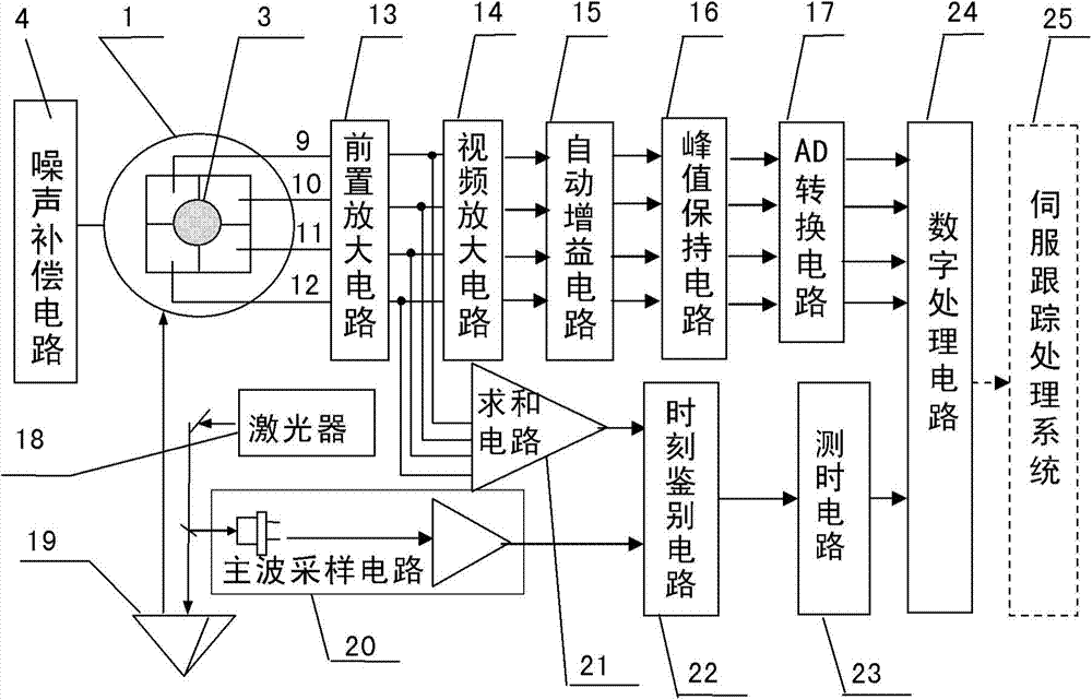
[0060] The circuit diagram of the analog circuit, video amplifier circuit, summation circuit, automatic gain amplifier circuit, AD conversion circuit, time discrimination circuit, CPU+FPGA digital circuit can be designed directly in the application circuit in the datasheet of the device, and the analog circuit It is the core of the whole circuit, so the attached drawing only shows the circuit diagram of the analog circuit part.

[0061] Below in conjunction with accompanying drawing, provide a kind of target line of sight angle offset and the method for distance measurement, its steps and conditions are as follows:

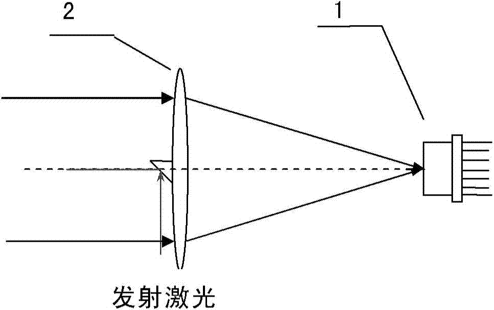
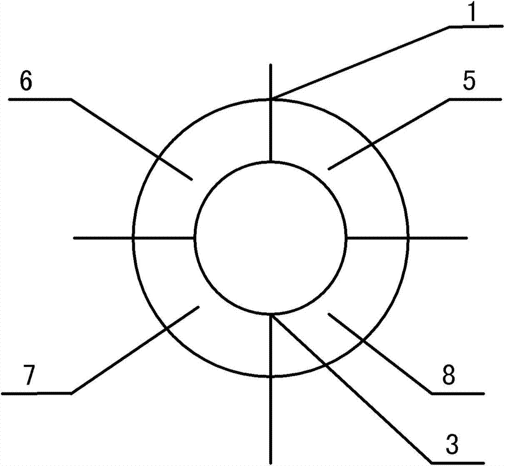
[0062] exist figure 1 and image 3 It shows that the target line-of-sight angle offset and the distance ...


PUM


Abstract

The invention provides a measuring device and method for the target line-of-sight angel offset and distance. The device is composed of a four-quadrant avalanche photodetector, a receiving and sending optical unit, a noise compensation circuit, a four-circuit front amplification circuit, a video amplification circuit, an automatic gain amplification circuit, a peak keeping circuit, an AD conversion circuit, a laser, a dominant wave sampling circuit, a summing circuit, a time identifying circuit, a time test circuit and a digital processing circuit, wherein the receiving and sending optical unit enables narrow pulse laser rays emitted by the laser to be converged on the photoelectric detector to form echo light spots after target reflection, photovoltaic conversion of the four-quadrant avalanche photodetector, front amplification, video amplification and automatic gain amplification are conducted, narrow-pulse peak keeping is conducted, transmission of the AD conversion circuit is conducted, and the digital processing circuit extracts the digital line-of-sight angel offset; summing is conducted on the four-circuit front amplification circuit, the dominant wave sampling circuit is combined, the time identifying circuit determines laser emitting and echo coming and returning time, the time is transmitted to the time identifying circuit to be measured, and the digital processing circuit decodes the corresponding distance.

Description

technical field [0001] The invention belongs to the technical field of photoelectric tracking and measurement, and relates to a device and method for measuring the offset of target line-of-sight angle and distance, especially capable of realizing the extraction of target line-of-sight angle offset and distance measurement in space rendezvous and docking. Background technique [0002] At present, the main photodetectors used to measure the offset of the target line-of-sight angle include charge-coupled device (CCD), active pixel sensor (APS), position sensor (PSD), and quadrant detector (QD). The data output by the charge-coupled device can directly reflect the position of the light spot on the photosensitive surface, and then obtain the offset of the target line-of-sight angle according to its offset relative to the center of the photosensitive surface. However, the charge-coupled device has many pixels, and the data that needs to be processed In addition, the sensitivity of...

Claims


Application Information

Patent Timeline
Patent Type & Authority Applications(China)
IPC IPC(8): G01S17/50G01S17/66
CPCG01S7/4861G01S7/4865G01S17/42G01S17/66
Inventor 冯志辉岳永坚杨武袁林晨代冬军
Owner INST OF OPTICS & ELECTRONICS - CHINESE ACAD OF SCI
Why Eureka
Try Eureka