Device and method using a spatial light modulator to find 3D coordinates of an object

Active Publication Date: 2013-01-17
FARO TECH INC
View PDF9 Cites 56 Cited by
  • Summary
  • Abstract
  • Description
  • Claims
  • Application Information

AI Technical Summary

Problems solved by technology

However, drawbacks with this type of approach include the fact that the diffraction grating is of a “static” type which must be moved by some type of manual means to effectuate a shift in the phase of the grating patterns.
This results in a relatively slow phase shifting speed, which leads to less than optimum performance of

Method used


Image

  • Device and method using a spatial light modulator to find 3D coordinates of an object
  • Device and method using a spatial light modulator to find 3D coordinates of an object
  • Device and method using a spatial light modulator to find 3D coordinates of an object

Examples


Embodiment Construction

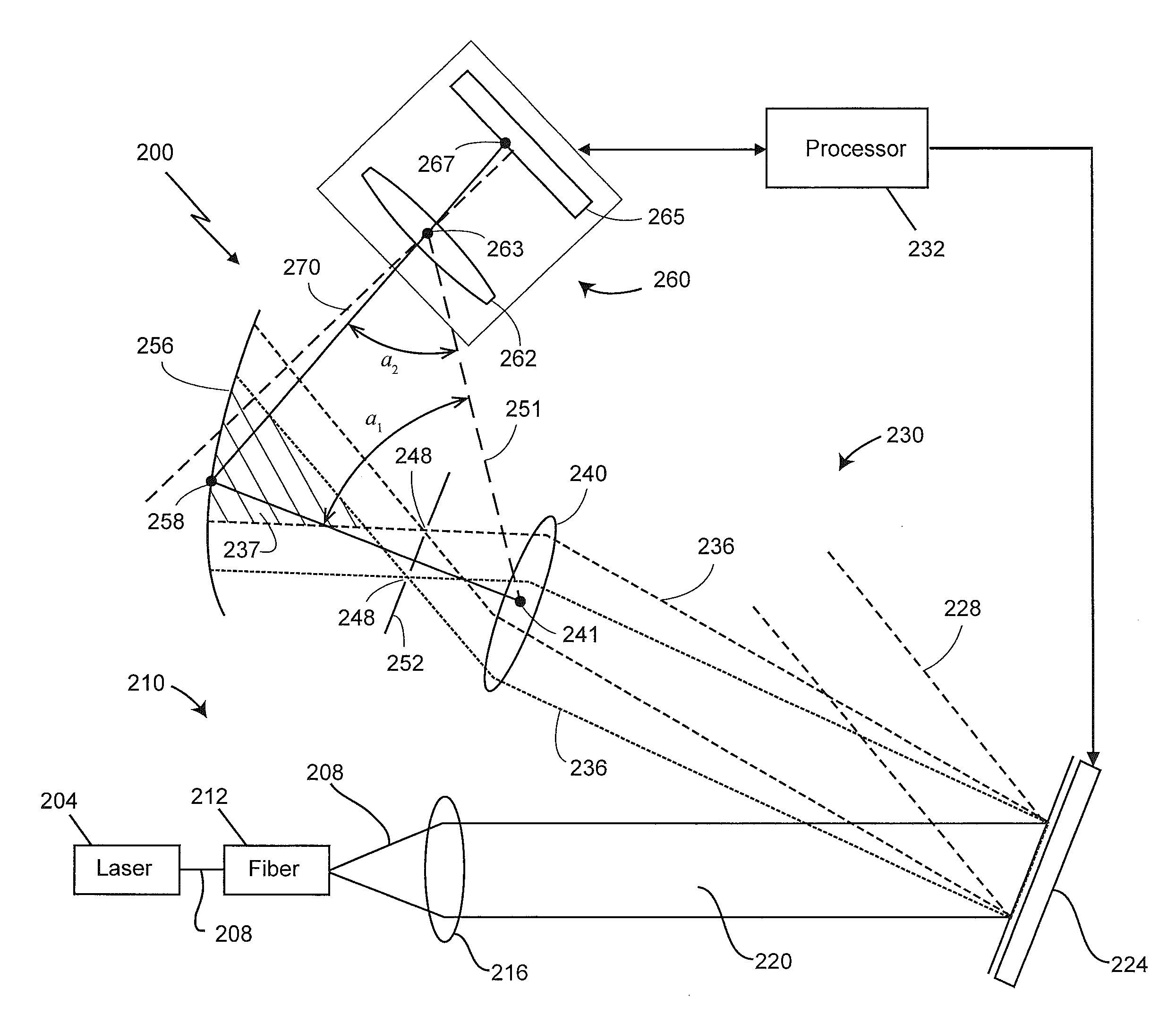
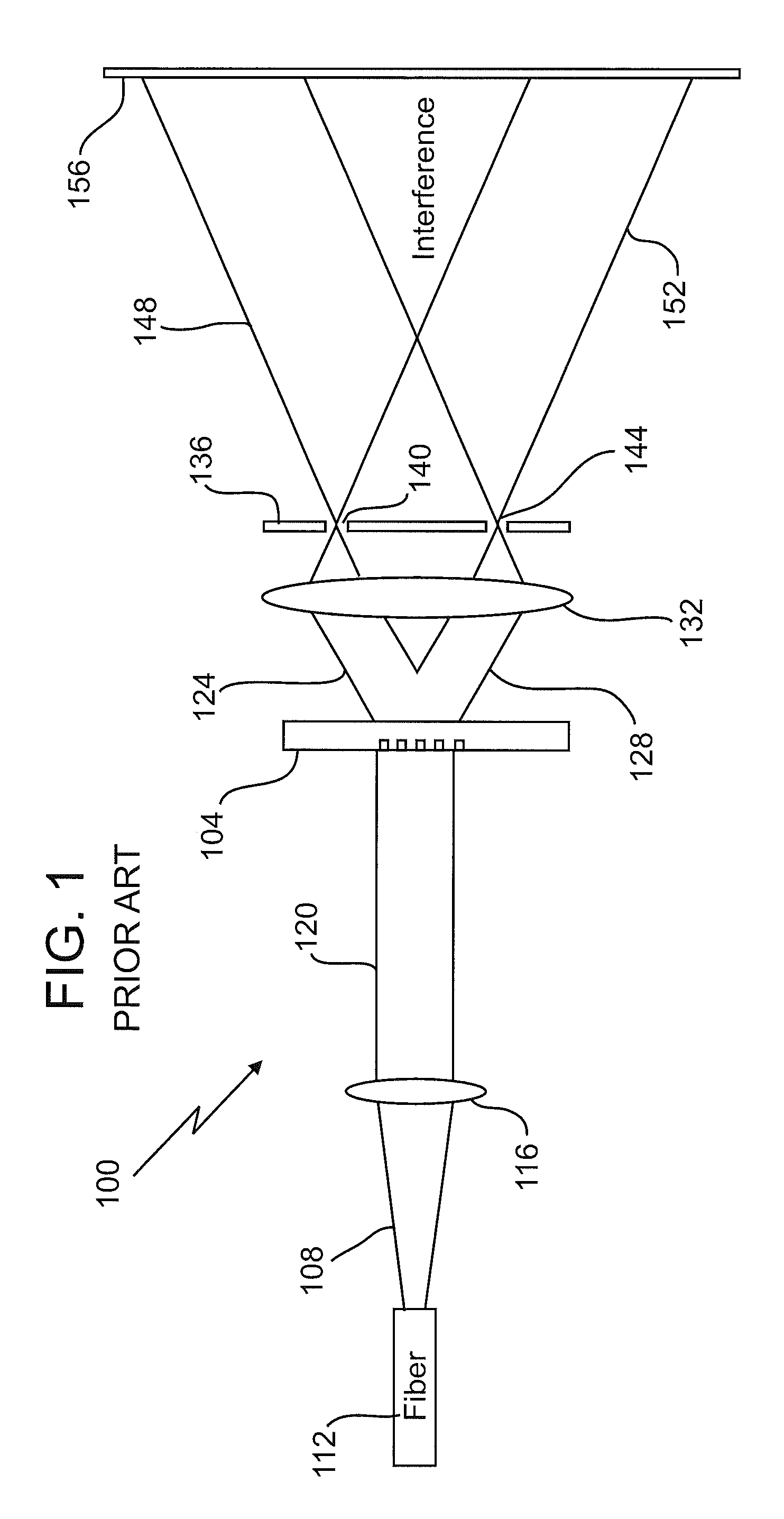
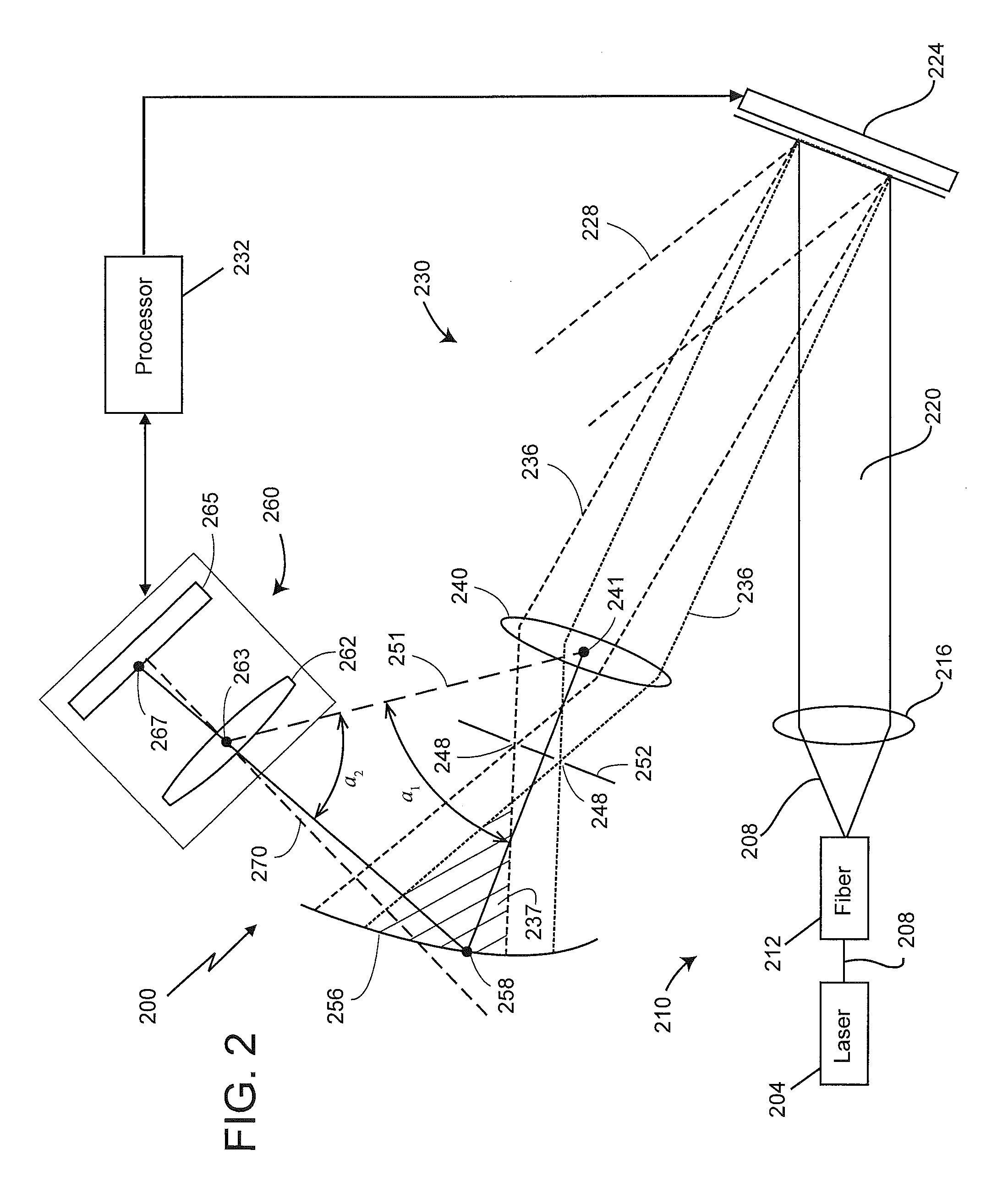
[0013]Referring to FIG. 1, there illustrated is a portion of a known, prior art system 100 for determining the 3D surface contour of an object using a static transmissive 2D diffraction grating 104. A beam of light 108 provided from a light source (e.g., a laser—not shown) passes through an optical fiber 112. The light beam 108 then passes through a collimating lens 116 that collimates the light beam 108 and passes the collimated light beam 120 to the diffraction grating 104. The grating 104 is typically static by nature and may be moved (e.g., back and forth) by any number of means (not shown), such as a motor. The grating forms the light beam 120 into one of various types of grating patterns of structured light. Movement of the static transmissive diffraction grating 104 causes a shift in the phases of the grating patterns. The system 100 of FIG. 1 may operate according to the known accordion fringe interferometry (AFI) technique.

[0014]More specifically, in the prior art embodimen...


PUM


Abstract

A method for determining three-dimensional coordinates of an object point on a surface of an object, the method including steps of: providing a source, a projector, and a camera; in each of two instances: spatially modulating source light; sending a modulator pattern of light through the projector lens to form light spots; filtering the spots with a pinhole plate; propagating light from the light spots onto the object to produce a fringe pattern; imaging the object point with a camera lens onto an array point of the photosensitive array to obtain first and second electrical data values from the photosensitive array; and determining the three-dimensional coordinates of the first object point based at least in part on the first electrical data value, the second electrical data value, and a baseline length.

Description

CROSS-REFERENCE TO RELATED APPLICATIONS[0001]The present application claims the benefit of U.S. Provisional Patent Application No. 61 / 507,304, filed on Jul. 13, 2011, the contents of which are hereby incorporated by reference in their entirety.BACKGROUND[0002]The present disclosure relates in general to three-dimensional (3D) surface contouring techniques, and more particularly to a device and method for using a spatial light modulator as a dynamic diffraction grating to reflect structured light in one of many types of patterns onto a surface of an object to ultimately determine through triangulation the 3D contour of the object's surface using the interference of two beams or spots of light.[0003]In the field of three-dimensional surface contouring for accurately and rapidly determining the 3D coordinates of an object, there are many known techniques available, some of which involve the use of projecting various structured light patterns onto the object. The structured light patter...

Claims


Application Information

Patent Timeline
IPC IPC(8): G01B11/25
CPCG01B11/2527G01B11/002G01B11/24
Inventor GONG, YUKRUSE, RYAN
Owner FARO TECH INC
Why Eureka
Try Eureka