Variable stiffness bellows

a flexible tube technology, applied in the direction of heat exhanger conduits, heating types, lighting and heating apparatus, etc., can solve the problems of material creep, air duct elongation, longitudinal tension on air ducts,

Inactive Publication Date: 2006-12-12
DUPONT POLYMERS INC
View PDF15 Cites 28 Cited by
  • Summary
  • Abstract
  • Description
  • Claims
  • Application Information

AI Technical Summary

Problems solved by technology

Further, such exposed surfaces create an axial force that causes a longitudinal tension on the air duct because of end-cap effects.
Tensile and shear forces also create constant stress on the air duct which leads to creep of material of the air duct, causing the air duct to elongate over time.
This force generates material stress which leads to material creep over time, and which can make tube 11 fall out of its design tolerance.
When used in an engine, the duct may contact hot surfaces or sharp angles and be damaged.
The design of FIGS. 2A–2B suffers from the problem that it is difficult to design tube 21 to get the right compromise of pressure resistance, stiffness and bending properties.
However, tube 31 suffers from the problems that it is difficult to adjust in terms of pressure resistance, bending stiffness and that the bending stiffness in the Z axis is too high due to limitations in the design and the method of manufacturing such flexible tubes 31.

Method used


Image

  • Variable stiffness bellows
  • Variable stiffness bellows
  • Variable stiffness bellows

Examples


Embodiment Construction

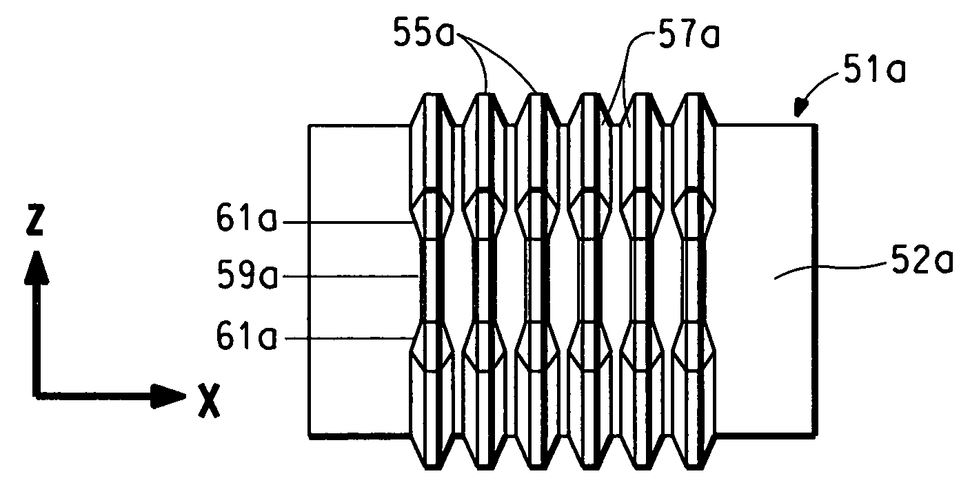
[0040]The present invention is directed to a flexible tube having a bellows that includes a plurality of convolutes formed in the wall of said tube and extending above the top surface of the tube. The convolutes are spaced apart from one another in the axial direction of the tube, and at least one of the convolutes has two opposing bending sections and two restrained elongation sections positioned between the bending sections, where the height of the bending sections above the top surface of the tube is greater that the height of the restrained elongation sections above the top surface of the tube.

[0041]The bending sections are preferably opposite each other at an angle of 150–210°, preferably 180° and, similarly, the restrained elongation sections are preferably opposite each other at an angle of 150–210°, preferably 180°.

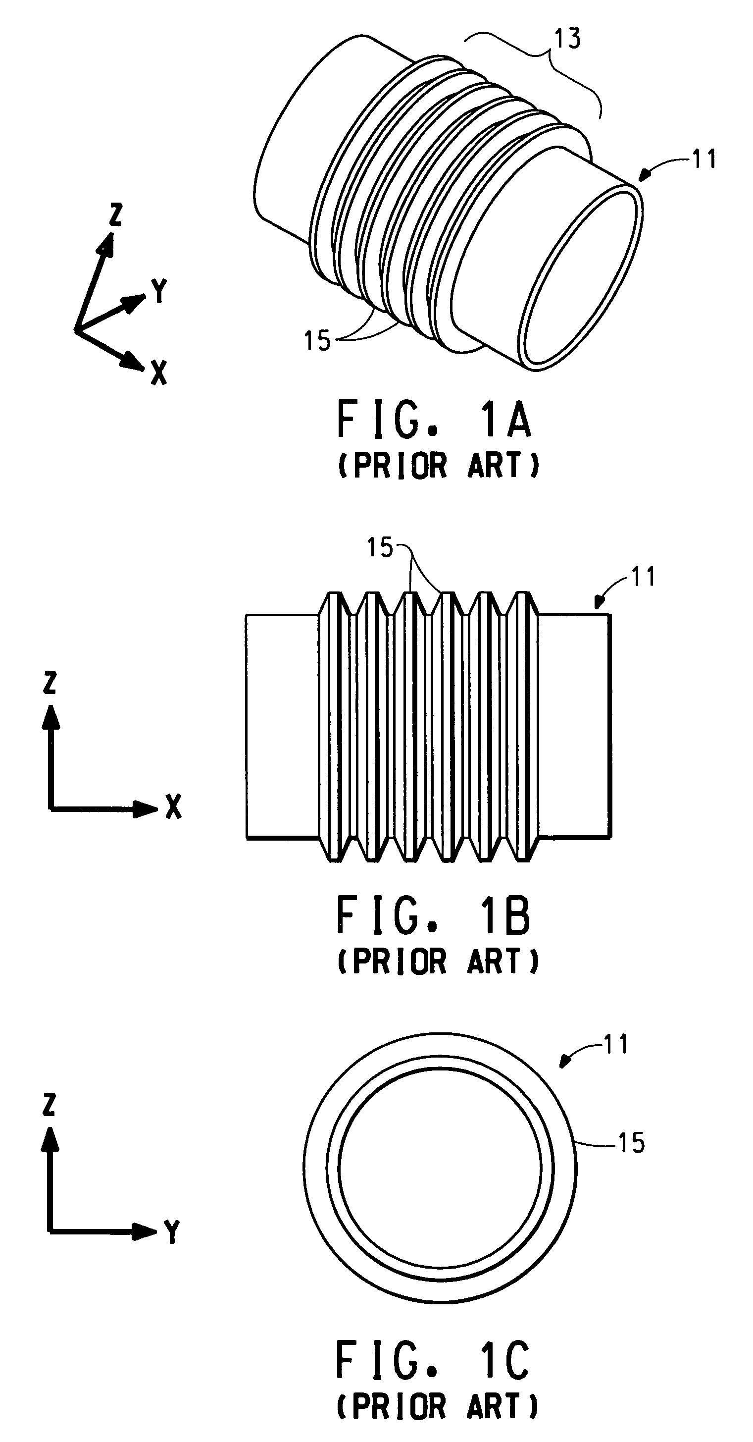
[0042]The inventive flexible tube maintains the benefits of flexible tube 31 discussed above, namely, a simple design and applicability to a wide range of profile...


PUM

PropertyMeasurementUnit
angleaaaaaaaaaa
angleaaaaaaaaaa
flexibleaaaaaaaaaa

Abstract

This invention relates to a flexible tube that includes a bellows having a plurality of convolutes formed in the wall of said tube and extending above the top surface of the tube, said convolutes being spaced from one another in the axial direction of the tube, wherein at least one of said convolutes comprises two opposing bending sections and two restrained elongation sections positioned between the bending sections, and wherein the height of the bending sections above the top surface of the tube is greater that the height of the restrained elongation sections above the top surface of the tube.

Description

CROSS REFERENCE TO RELATED APPLICATIONS[0001]This application is a continuation of application Ser. No. 09 / 681,934, filed Jun. 28, 2001, now abandoned, which claims the benefit of priority to U.S. Provisional Application No. 60 / 215,587, Jun. 30, 2000.BACKGROUND[0002]1. Field of the Invention[0003]This invention relates to the field of flexible tubes that may be used as air ducts, coolant pipes, fuel tubes, filler necks and the like, such as are used in the automotive industry.[0004]2. Description of the Related Art[0005]Flexible tubes are used, for example, as air ducts in automobiles where the air duct carries air to an engine. The air may pass through a turbocharger, in which case the air flowing through the duct is heated to temperatures of generally 140–160C, but possibly up to 180–200C.[0006]These air ducts are often made by various blow molding techniques. Sequential extrusion blow molding technology is used to produce one-piece air ducts that combine several hard and soft seg...

Claims


Application Information

Patent Timeline
Patent Type & Authority Patents(United States)
IPC IPC(8): F16L11/11B60H1/00F16L11/15F16L51/02
CPCB60H1/00557F16L11/111F16L11/15F16L51/025F24F13/0218F16L2011/047B29C49/04B29L2031/755B29L2023/18B29C47/0023B29C47/0054Y10S138/11B29C48/0017B29C48/09
Inventor RENAUD, MICHEL C.
Owner DUPONT POLYMERS INC
Why Eureka
Try Eureka