Prosthetic foot with energy transfer

a technology of prosthetic feet and energy transfer, applied in the field of prosthetic feet, can solve the problems of limited material and imagination in the development of functional and natural artificial feet, athletic feet are too hard for everyday use, and feet designed for particular purposes are typically unsuited for other purposes

Inactive Publication Date: 2010-03-30
FREEDOM INNOVATIONS INC
View PDF186 Cites 52 Cited by
  • Summary
  • Abstract
  • Description
  • Claims
  • Application Information

AI Technical Summary

Benefits of technology

[0010]It has been recognized that it would be advantageous to develop a prosthetic foot with adjustable stiffness for accommodating different uses or different users.

Problems solved by technology

With respect to prosthetic feet, the development of a functional and natural artificial foot has been limited only by material and imagination.
Feet designed for particular purposes are typically unsuited for other purposes.
Stiff, athletic feet are too hard for everyday use, and soft, everyday feet are too fragile for athletic use.
Multiple-use feet have been designed which are capable of many different uses, but without being particularly well suited for any specialized use.

Method used


Image

  • Prosthetic foot with energy transfer
  • Prosthetic foot with energy transfer
  • Prosthetic foot with energy transfer

Examples


Embodiment Construction

[0046]Reference will now be made to the exemplary embodiments illustrated in the drawings, and specific language will be used herein to describe the same. It will nevertheless be understood that no limitation of the scope of the invention is thereby intended. Alterations and further modifications of the inventive features illustrated herein, and additional applications of the principles of the inventions as illustrated herein, which would occur to one skilled in the relevant art and having possession of this disclosure, are to be considered within the scope of the invention.

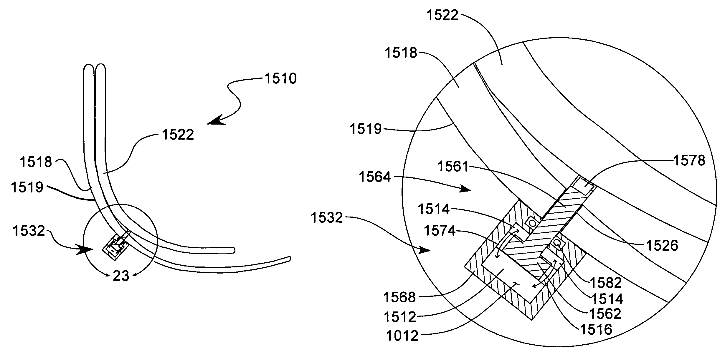
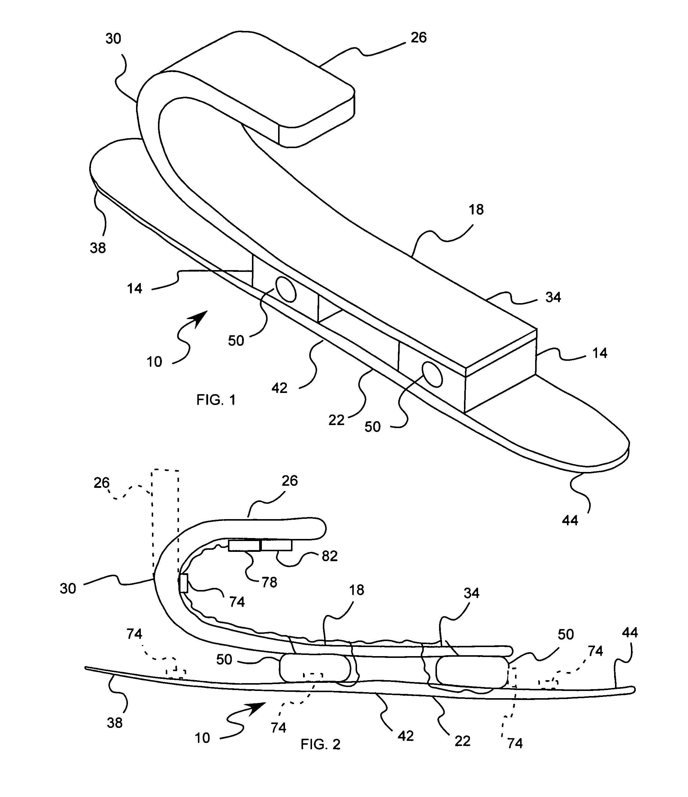
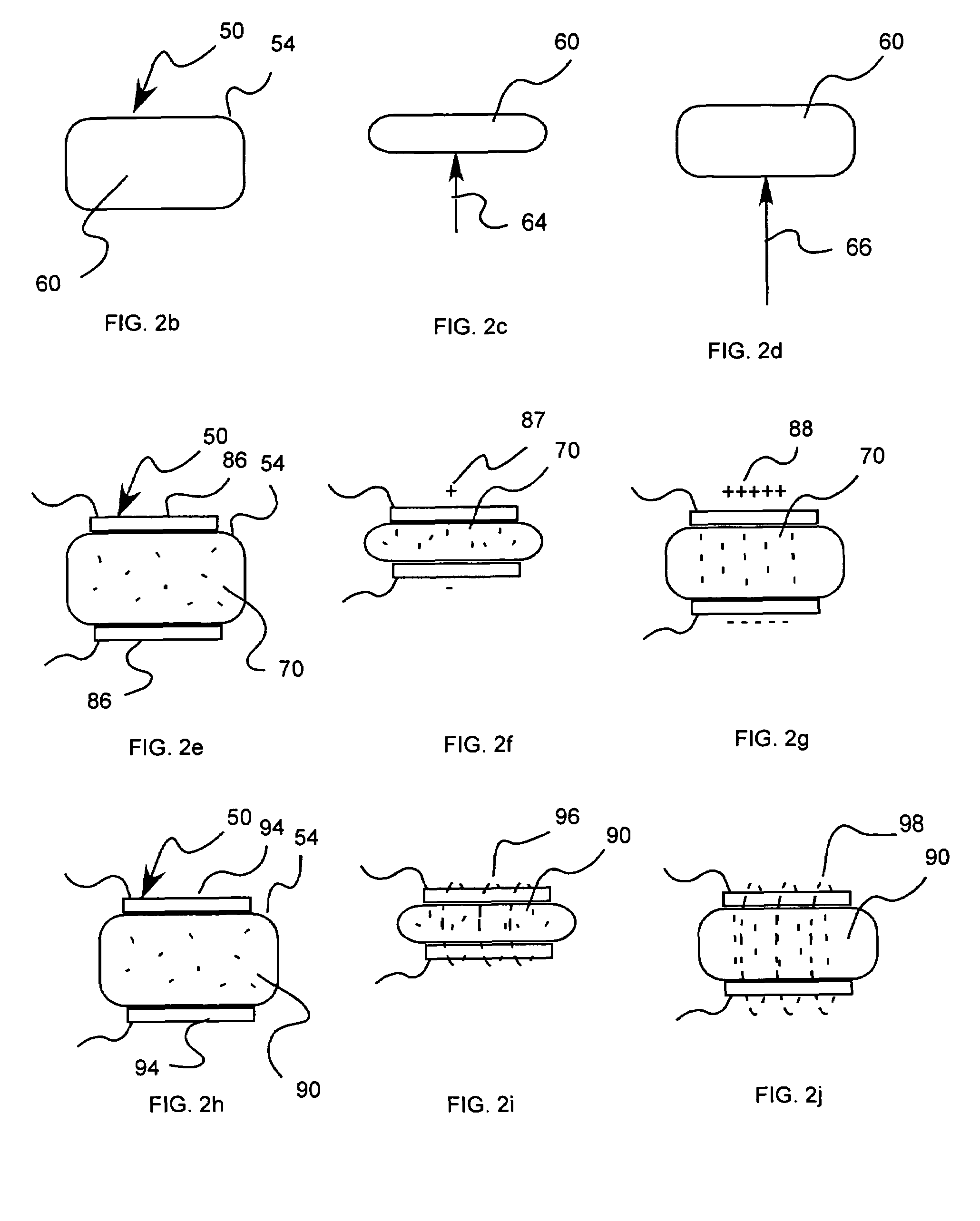
[0047]As illustrated in the figures, various embodiments of prosthetic feet in accordance with the present invention are shown with an energy transfer medium that includes a variable viscosity fluid or material, or an energy transfer mechanism. The energy transfer medium, or variable viscosity fluid or material, is located between first and second members of the foot so that energy is transferred between the firs...


PUM


Abstract

A prosthetic foot device with variable stiffness response includes a variable energy transfer mechanism disposed between first and second foot members to transfer a variable amount of energy between the members during use. A chamber is associated with one of the first and second foot members, and a piston is associated with another of the first and second foot members and is movable in the chamber. At least one aperture is formed between the piston and the chamber. A variable viscosity fluid is disposed in the chamber and displaceable through the at least one aperture between the piston and the chamber to allow fluid to flow within the chamber between opposite sides of the piston. The variable viscosity fluid has a viscosity that is variable to vary an ability of the variable viscosity fluid to flow through the at least one aperture.

Description

[0001]This application is a continuation-in-part of U.S. patent application Ser. No. 11 / 377,228 filed Mar. 15, 2006 now U.S. Pat. No. 7,572,299 which is a continuation-in-part of U.S. patent application Ser. No. 11 / 098,828, filed Apr. 4, 2005, now U.S. Pat. No. 7,341,603 which is a continuation-in-part of U.S. application Ser. No. 10 / 738,645, U.S. Pat. No. 6,875,242, filed Dec. 16, 2003, which is a continuation of U.S. application Ser. No. 10 / 137,933, U.S. Pat. No. 6,663,673, filed May 3, 2002, which is a continuation-in-part of U.S. patent application Ser. No. 09 / 607,494, filed Jun. 30, 2000, now abandon, which are herein incorporated by reference.BACKGROUND OF THE INVENTION[0002]1. Field of the Invention[0003]The present invention relates generally to prosthetic feet. More particularly, the present invention relates to prosthetic feet with an energy transfer mechanism.[0004]2. Related Art[0005]Many individuals have lost a limb for various reasons including war, accident, or diseas...

Claims


Application Information

Patent Timeline
Patent Type & Authority Patents(United States)
IPC IPC(8): A61F2/66
CPCA61F2/66A61F2/68A61F2/6607A61F2002/5004A61F2002/5006A61F2002/503A61F2002/5033A61F2002/5055A61F2002/6642A61F2002/665A61F2002/6664A61F2002/6671A61F2002/6678A61F2002/745A61F2/70A61F2/74
Inventor CHRISTENSEN, ROLAND J.
Owner FREEDOM INNOVATIONS INC
Why Eureka
Try Eureka