Adjustment method for dynamic stiffness of rubber joint with liquid damping, and rubber joint

A rubber joint, liquid damping technology, applied in the direction of shock absorber, spring, spring/shock absorber, etc., can solve problems such as changing dynamic stiffness, and achieve the effect of adjustable dynamic stiffness, easy implementation and simple structure

Active Publication Date: 2012-08-22
ZHUZHOU TIMES NEW MATERIALS TECH
View PDF7 Cites 32 Cited by
  • Summary
  • Abstract
  • Description
  • Claims
  • Application Information

AI Technical Summary

Problems solved by technology

[0005] The purpose of the present invention is to solve the problem that the existing rubber joint with liquid damping cannot change its dynamic stiffness under certain circumstances, and propose a dynamic and static stiffness ratio of rubber joint with liquid damping that can make the dynamic and static stiffness of the rubber joint with liquid damping adjustable. Adjustment method and device

Method used


Image

  • Adjustment method for dynamic stiffness of rubber joint with liquid damping, and rubber joint
  • Adjustment method for dynamic stiffness of rubber joint with liquid damping, and rubber joint
  • Adjustment method for dynamic stiffness of rubber joint with liquid damping, and rubber joint

Examples


Embodiment 1

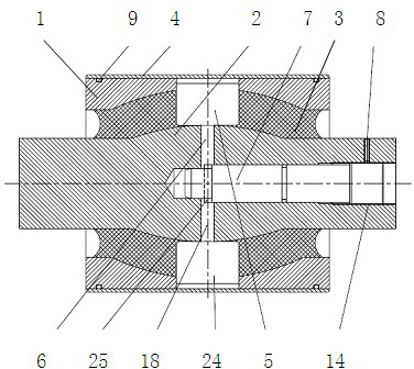
[0027] attached figure 1 An embodiment of the present invention is given, and it can be seen from the accompanying drawings that a rubber joint assembly with a liquid cavity and an adjustable flow channel inside includes a rubber joint jacket 1, a mandrel 2, and an elastic rubber 3; The rubber 3 is set on the mandrel 2; its characteristic is that there is a metal jacket 4 on the rubber joint jacket 1, and the rubber joint is pressed into the metal jacket; on the rubber joint jacket 1, two The independent liquid chambers 5 above communicate with each other through the throttling channel 6 arranged on the mandrel, and the throttling channel adjusting shaft 7 is set inside the mandrel 2 of the rubber joint and fixed by a set screw 8; Each part is sealed by an O-ring 9 to prevent leakage. The specific structure of the metal jacket 4 is a simple cylindrical tube, and rubber joints are press-fitted inside it.

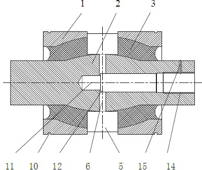
[0028] attached figure 2 It is the specific structure of the rubber ...

Embodiment 2

[0033] The difference between the second embodiment and the first embodiment is that the throttling channel is formed in a different way (as attached Figure 5 shown), the throttling passage of embodiment one is formed by the step of the hole and the step of the shaft to form a channel with a square section, and the throttling passage of embodiment two is composed of the spherical end of the mandrel hole 28 and the spherical end of the adjustment shaft 27 The gap 26 between the mandrel hole 28 is composed of the spherical diameter of the end of the mandrel hole 28 and the spherical diameter of the end of the adjustment shaft 27. By adjusting the shaft 27 to move axially in the mandrel hole 28, the distance between the shaft and the hole can be adjusted. The clearance changes to achieve the purpose of damping adjustment.

Embodiment 3

[0035] The difference between the third embodiment and the first embodiment is that the damping force is not provided by the throttling passage, but by the throttling opening of the passage on the adjustment shaft, and the size of the throttling opening is adjustable.

[0036] attached Image 6 The implementation diagram of Embodiment 3 of another solution of the present invention is given. The structure is similar to Embodiment 1, the difference is that the adjustment shaft 29 is the optical axis in the mandrel hole, and the end of the shaft is not threaded; the adjustment shaft 29 An orifice 30 is added to itself, a spring 31 is added to the end of the adjustment shaft 29, and a positioning pin 32 is added to the mandrel 2 to prevent the adjustment shaft from swinging in the mandrel hole; The throttling hole 30 is combined with the throttling channel hole 32 on the mandrel 2 to form a throttling port, and at the same time, an axial stopper 54 is added to the outer end of the...


PUM


Abstract

An adjustment method for the dynamic stiffness of a rubber joint with liquid damping, and the rubber joint, and the rubber joint comprises metal outer sleeves, a rubber joint body, a throttling channel adjustment device and other parts, wherein the specific structure is as follows: proper holes are arranged on the outer surface of the rubber joint body and pressed-installed with the metal outer sleeves on the outer surfaces thereof to form closed cavities, the cavities are arranged in the relative movement directions of the mandrel and the outer sleeve of the rubber joint body, and symmetrically distributed at the both sides of the axis of the rubber joint body, and the two cavities are connected via a throttling channel; and in this way, when the mandrel and the outer sleeve of the rubber joint perform a relative movement, the volume of one side of each of the cavities at the both sides of the mandrel is reduced, and the volume of the other side is increased, so that a liquid damping medium at the side with the reduced volume flows to the side with the increased volume via pores, and the liquid damping medium generates a damping force while passing through the throttling channel due to damping action. The size of the throttling channel can be changed via the adjustment device, so as to achieve the purposes of adjusting the damping force and obtaining the needed dynamic stiffness.

Description

technical field [0001] The invention relates to a method and device for adjusting the performance of rubber damping components of rail vehicles and automobiles, in particular to a method and device for adjusting the dynamic and static stiffness ratio of rubber joints with liquid damping for rail vehicles and automobiles; the method and device A liquid cavity and an adjustable flow channel are arranged inside the rubber joint assembly to change the dynamic stiffness of the rubber joint assembly. technical background [0002] Rubber joint is a rubber damping element widely used in rail vehicles and automobiles. In some cases, it is required that the static stiffness of the rubber damping element is small and the dynamic stiffness is large, that is, the ratio of dynamic and static stiffness is large. It is used in rail vehicle bogies. As an example, when the bogie is running on a straight line, in order to ensure the running stability, the boom node is required to provide a lar...

Claims


Application Information

Patent Timeline
Patent Type & Authority Applications(China)
IPC IPC(8): F16F13/08F16F13/26
Inventor 刘建勋林立钿荣继刚
Owner ZHUZHOU TIMES NEW MATERIALS TECH
Why Eureka
Try Eureka