Snowmobile suspension system

a suspension system and snowmobile technology, applied in the field of snowmobiles, can solve the problems of affecting the handling ability of snowmobiles, affecting the stability of snowmobiles, and the suspension system is usually not adjustable, so as to achieve the effect of improving the handling ability

Inactive Publication Date: 2008-01-29
LILLBACKA JETAIR
View PDF14 Cites 29 Cited by
  • Summary
  • Abstract
  • Description
  • Claims
  • Application Information

AI Technical Summary

Benefits of technology

[0005]To provide a smooth or cushioned ride for a rider of the snowmobile and also the ability of the rider to adjust at any time the stiffness of the ride, at least one but most likely a plurality of fluid actuated devices are interposed between the body and the frame of the snowmobile. These fluid actuated devices could be hydraulic or gas driven cylinders controlled either manually by the rider or automatically by a feedback circuit.

Problems solved by technology

Such suspension system is usually not adjustable.
Thus, if persons of different weights, or for that matter if more than one person, were to ride on the same snowmobile, the ride would become choppy and the steering of the snowmobile becomes less responsive.
Such unresponsiveness in the steering and choppiness in the ride detract from the rider the pleasure of driving or riding a snowmobile.
The fact that the conventional suspension system of snowmobiles is unable to adjust on a real time basis means that a rider has to stop the snowmobile, turn off the engine for safety sake and manually adjust the stiffness or tension provided by the shock absorbers of the snowmobile, if indeed such shock absorbers were adjustable.
But adjusting the conventional suspension system for one environment means that the rider has to readjust the suspension system when the snowmobile is ridden in a different environment, as the suspension system, once set, remains set at that tension or stiffness, until readjustment.

Method used


Image

  • Snowmobile suspension system
  • Snowmobile suspension system
  • Snowmobile suspension system

Examples


Embodiment Construction

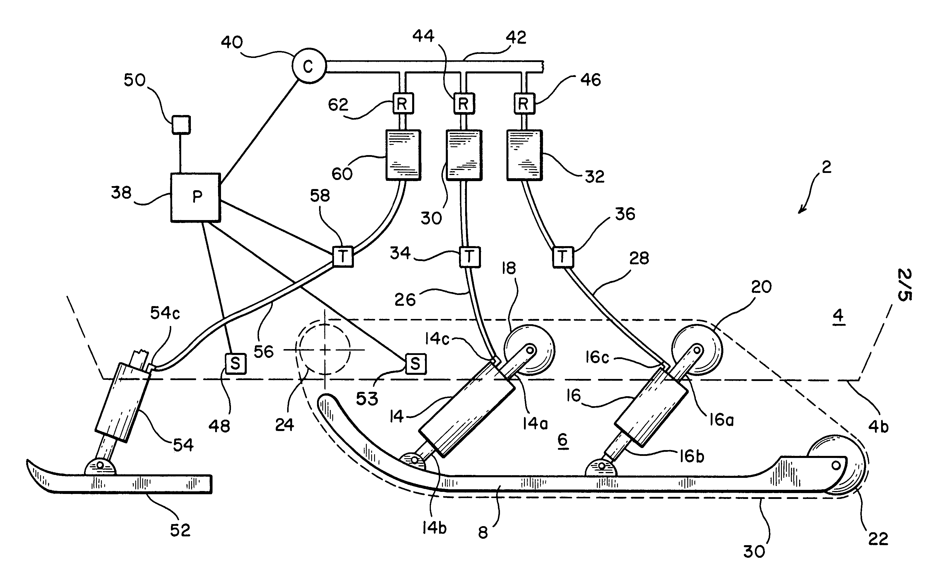
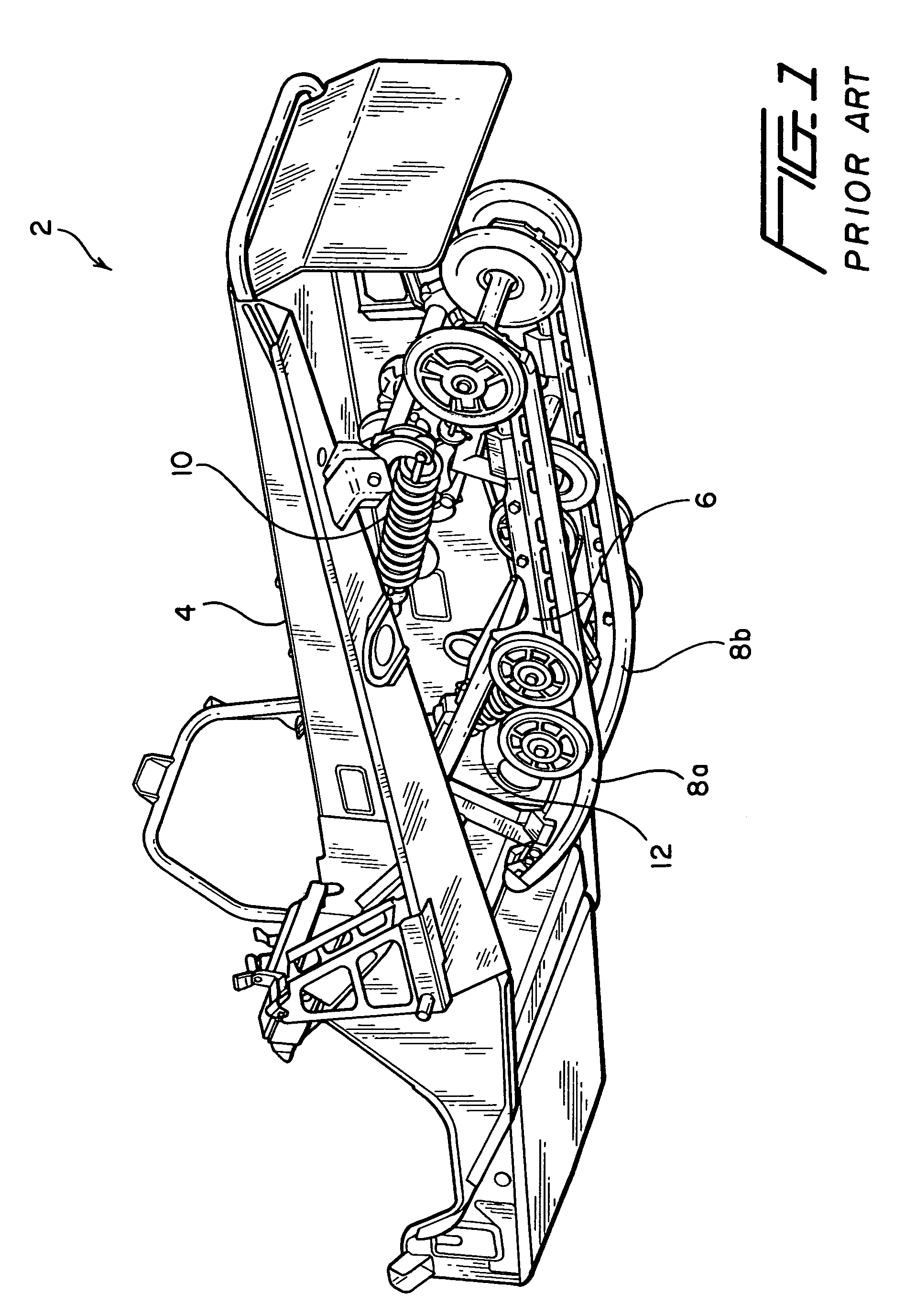
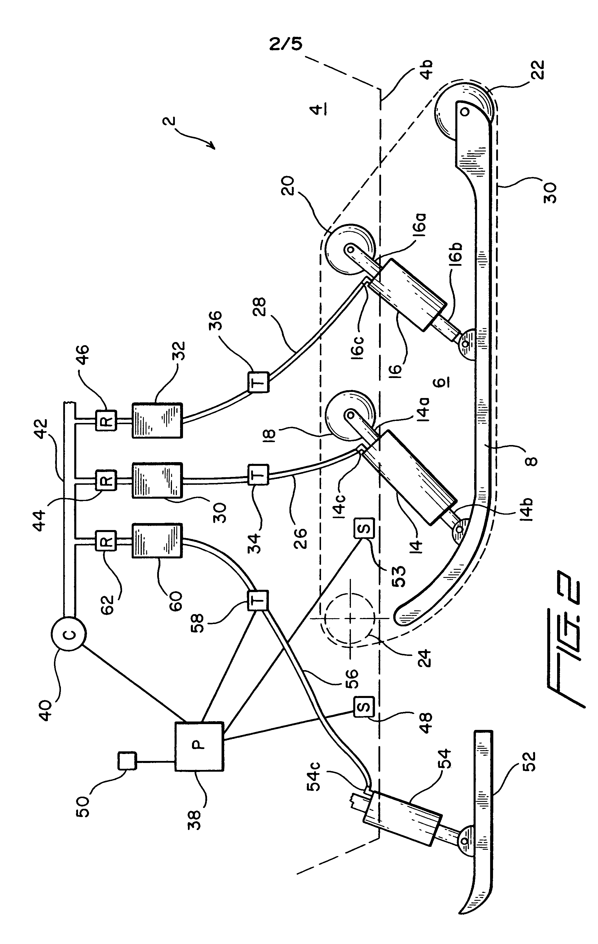
[0023]Stripped of all components not required for the understanding of the instant invention, an exemplar snowmobile showing only the body and the frame attached thereto is shown in FIG. 1. As illustrated, snowmobile or vehicle 2 has a body 4 mounted to a frame 6 by way of a number of connecting links and struts. Fixedly coupled to frame 6 are two slide tracks 8a and 8b about which a belt, not shown, is mounted. As is well known, the belt is driven by at least one wheel, which in turn is driven by a belt or gears from a transmission, shown in FIG. 5, which movement is driven by an engine, not shown for the sake of simplicity in illustration. Thus, when driven, the belt is guided by slide tracks 8a and 8b, as well as guide wheels, and rotates about the frame of snowmobile 2 such as for example shown by the dotted line 30 in FIG. 3.

[0024]Also shown in FIG. 1 are a number of shock absorbers 10 and 12 interposed between body 4 and frame 6 for providing a smoother ride for a rider of the...


PUM


Abstract

To enable a rider to control in real time the type of ride he desires, a snowmobile is equipped with a suspension system that includes at least one fluid actuated device which can be adjusted in real time to control the relative distance between the body of the snowmobile onto which the rider sits and the frame, or the slide tracks about which the drive belt is mounted. By setting a constant predetermined desirable distance between the body and the slide tracks, or the frame, of the snowmobile, an optimal cushioned ride for the rider is obtained. The control of the fluid actuated device(s) may be effected at any time manually by the rider, or be effected by a feedback system. The snowmobile is also equipped with an ABS system for enhancing the traction of the drive belt on snow and therefore the control of the snowmobile by the rider.

Description

RELATED APPLICATIONS[0001]This is a divisional of application Ser. No. 09 / 065,557 filed Apr. 24, 1998, now U.S. Pat. No. 6,253,867.FIELD OF THE INVENTION[0002]The present invention relates generally to snowmobiles and more particularly to a suspension system that provides a controlled cushioned ride for riders of the snowmobile.BACKGROUND OF THE INVENTION[0003]To compensate for the ruggedness of the terrain, a conventional suspension system for a snowmobile includes a pair of shock absorbers, and associated springs, for supporting the frame of the snowmobile. Such suspension system is usually not adjustable. Thus, if persons of different weights, or for that matter if more than one person, were to ride on the same snowmobile, the ride would become choppy and the steering of the snowmobile becomes less responsive. Such unresponsiveness in the steering and choppiness in the ride detract from the rider the pleasure of driving or riding a snowmobile.[0004]The fact that the conventional ...

Claims


Application Information

Patent Timeline
Patent Type & Authority Patents(United States)
IPC IPC(8): B62M29/00B60G17/04B60G15/12B60G17/052B60T8/32B62D55/07B62D55/112B62M27/02
CPCB60G15/12B60G17/0523B60G2202/314B60G2202/412B60G2300/32B60G2400/252B60G2400/61B60G2500/202B60G2500/203B60G2500/204B60G2500/30B60G2800/164B60G2800/914B60T8/3225B62D55/07B62D55/112B62M27/02B62M2027/026
Inventor LILLBACKA, JORMALILLBACKA, PEKKA
Owner LILLBACKA JETAIR
Why Eureka
Try Eureka