Heat exchanger of a multiple type

a heat exchanger and multiple type technology, applied in indirect heat exchangers, lighting and heating apparatus, stationary conduit assemblies, etc., can solve the problems of difficult to reserve a large space (a crushable zone) to absorb, and the heat exchange core of the second heat exchanger may not be supplied with air for heat exchange at a sufficient flow rate, etc., to achieve the effect of simplifying the structur

Active Publication Date: 2006-12-12
DENSO CORP
View PDF9 Cites 15 Cited by
  • Summary
  • Abstract
  • Description
  • Claims
  • Application Information

AI Technical Summary

Benefits of technology

[0021]Another object of the present invention is to enhance the heat exchange capability of a multiple heat exchanger by minimizing a dead space occupied by a coupling means between a first heat exchanger and a second heat exchanger in the multiple heat exchanger.
[0067]According to a twenty-fourth aspect of the present invention, heat exchangers of different sizes in the air flow direction and having reinforcement members of different widths can be coupled using coupling members in a simplified structure.

Problems solved by technology

Therefore, as the space between the heat exchange core of the first heat exchanger and the heat exchange core of the second heat exchanger are blocked by the two reinforcement plates and the two brackets, in the case where an additional heat exchanger needs to be arranged at the downstream side of the air flow in the multiple heat exchanger, there is a possibility that a portion of the heat exchange core of the additional heat exchanger arranged at the downstream side corresponding to the space between the heat exchange core of the first heat exchanger and the heat exchange core of the second heat exchanger may not be supplied with air for heat exchange at a sufficient flow-rate.
In a vehicle, the heat exchange device including the multiple heat exchanger 2001 and the heat exchanger 2004 is generally mounted on a front end of the vehicle, and if the width D of the heat exchange device increases, it will be difficult to reserve a large space (a crushable zone) to absorb a shock caused by a head-on collision of the vehicle.

Method used


Image

  • Heat exchanger of a multiple type
  • Heat exchanger of a multiple type
  • Heat exchanger of a multiple type

Examples


first embodiment

[0101](First Embodiment)

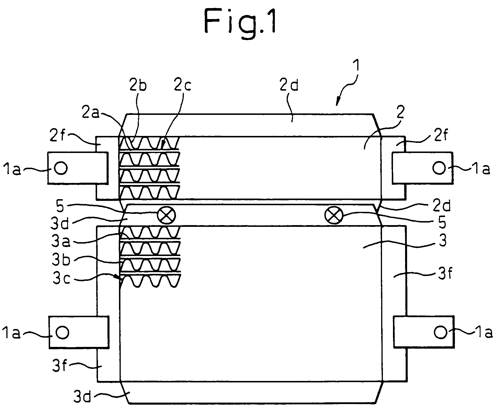
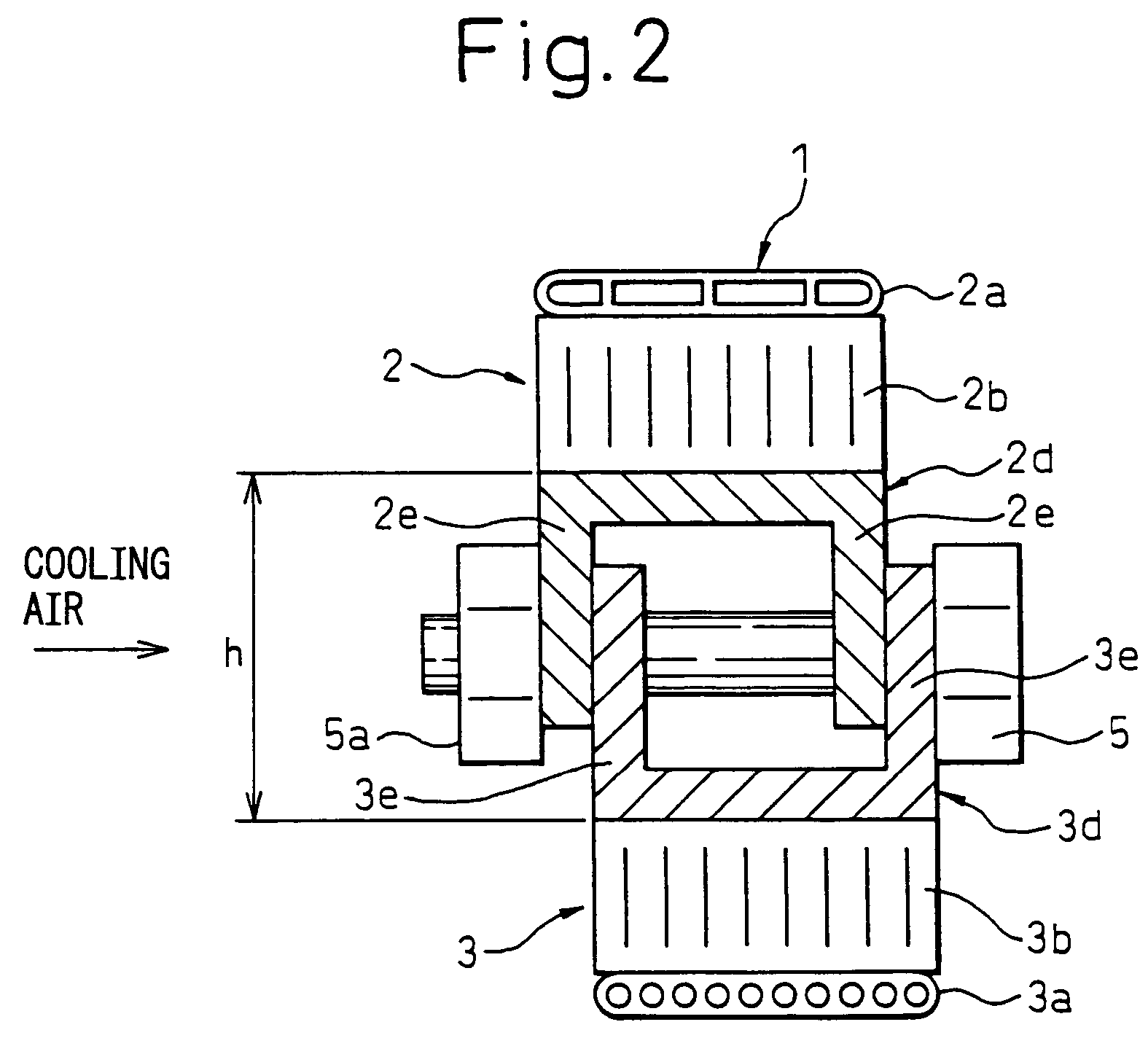
[0102]In a first embodiment, a multiple heat exchanger (heat exchanger module) according to the present invention is applied to a cooling device for a hybrid vehicle. FIG. 1 is a diagram showing the characteristics of a multiple heat exchanger 1 according to the present embodiment, FIG. 2 is a front view of the multiple heat exchanger 1 when viewed in the air flow direction, and FIG. 3 is a diagram showing a state in which the multiple heat exchanger 1 according to the present embodiment is mounted on a vehicle.

[0103]As shown in FIG. 1, the multiple heat exchanger 1 according to the present embodiment comprises: a first radiator 2 that effects heat exchange between inverter cooling water and air, which water cools an electric motor for running a vehicle (not shown) and drive circuits such as an inverter circuit for controlling a drive current to the electric motor; an outdoor heat exchanger 3 of an air conditioner for a vehicle (which is installed outside the...

second embodiment

[0123](Second Embodiment)

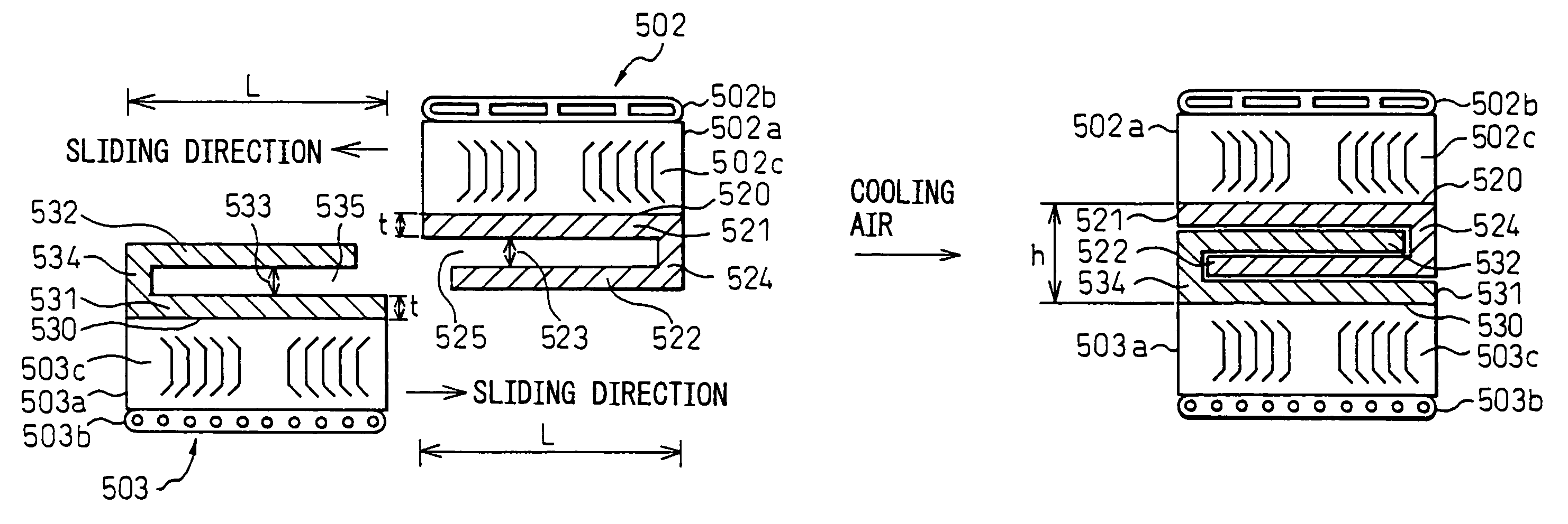
[0124]In the first embodiment, the wall surfaces 2e of the first radiator 2 and the wall surfaces 3e of the outdoor heat exchanger 3 are made to come next to and overlap each other in series in the cooling air flow direction so as to be positioned alternately in the cooling air flow direction, but in the present embodiment, as shown in FIG. 5, both the reinforcement plates 2d and 3d are mechanically joined in a state of being made to come next and overlap each other in series in the air flow direction so that the reinforcement plate 2d of the first radiator 2 is accommodated within the reinforcement plate 3d of the outdoor heat exchanger 3.

third embodiment

[0125](Third Embodiment)

[0126]In the second embodiment, both the reinforcement plates 2d and 3d are mechanically joined in a state of being next to and overlapping each other in series in the air flow direction so that the reinforcement plate 2d of the first radiator 2 is accommodated within the reinforcement plate 3d of the outdoor heat exchanger 3, but in the present embodiment, as shown in FIG. 6, both the reinforcement plates 2d and 3d are mechanically joined in a state of being made to come next to and overlap each other in series in the air flow direction so that the reinforcement plate 3d of the outdoor heat exchanger 3 is accommodated within the reinforcement plate 2d of the first radiator 2.


PUM


Abstract

Even in the case where an additional heat exchanger must be arranged at the downstream side in the air flow direction of a multiple heat exchanger, a high flow-rate of air can be supplied to the additional heat exchanger arranged at the downstream side. In a state in which a reinforcement plate 3d of an outdoor heat exchanger 3 and a reinforcement plate 2d of a first radiator 2 come next to and overlap each other in series in the cooling air flow direction, both the reinforcement plates 2d and 3d are joined with a bolt 5. Due to this, a distance h between a first heat exchange core 2c and a second heat exchange core 3c is reduced. Therefore, air for cooling can be supplied, at a high flow-rate, to a second radiator 3 arranged at the downstream side.

Description

BACKGROUND OF THE INVENTION[0001]1. Field of the Invention[0002]The present invention relates to a multiple heat exchanger (heat exchanger module) comprising two or more heat exchangers[0003]2. Description of the Related Art[0004]A heat exchanger such as a radiator or a condenser generally comprises a heat exchange core including a plurality of tubes through which a fluid flows and fins provided on the outer surfaces of the tubes, reinforcement plates for reinforcing the heat exchange core, etc. (for example, refer to Patent document 1).[0005]Conventionally, a heat exchanger is assembled to a vehicle etc. by assembling one end of a metal bracket to a reinforcement plate with a bolt, and the other end of the bracket to the body of the vehicle with a bolt.[0006]Patent Document 1[0007]Japanese Patent Publication No. 3301158[0008]Recently, there is an increasing need for a multiple heat exchanger comprising two or more heat exchangers, in which a condenser of an air conditioner for a ve...

Claims


Application Information

Patent Timeline
Patent Type & Authority Patents(United States)
IPC IPC(8): F28F9/26F28D1/04F28F9/00
CPCF28D1/0452F28F9/002
Inventor SANADA, RYOUICHIHAYASAKA, ATSUSHI
Owner DENSO CORP
Why Eureka
Try Eureka