Supercritical refrigerant cycle system

a cycle system and supercritical technology, applied in the direction of gas cycle refrigeration machines, refrigeration safety arrangements, refrigeration machines, etc., can solve the problem of not being able to exchange heat with air in sufficient degree, the required amount of circulating refrigerant must be increased, and the degree of superheat of a refrigerant at the outlet of the evaporator is not adjusted, so as to improve the refrigerating capacity (cooling capacity) of the evaporator, improve the coefficient of performan

Inactive Publication Date: 2005-07-14
SANYO ELECTRIC CO LTD
View PDF13 Cites 16 Cited by
  • Summary
  • Abstract
  • Description
  • Claims
  • Application Information

AI Technical Summary

Benefits of technology

[0014] Particularly, since it becomes possible to enhance the refrigerating capacity without increasing the amount of circulating refrigerant under a high heat load, an improvement in the coefficient of performance of the compressor can be achieved.
[0015] Further, the system of the present invention further comprises an intermediate heat exchanger for-allowing a refrigerant coming out of a gas cooler to exchange heat with a refrigerant coming out of the evaporator and a receiver tank for temporarily reserving a refrigerant to be sucked into the compressor and causes a refrigerant coming out of the evaporator and passing through the intermediate heat exchanger to flow into the receiver tank. As a result, a low temperature refrigerant coming out of the evaporator is allowed to flow into the intermediate heat exchanger without passing through the receiver tank so as to cool a refrigerant coming out of the gas cooler more effectively. Thereby, a further improvement in the refrigerating capacity (cooling capacity) of the evaporator can be achieved.
[0016] Further, in the present invention, in addition to the above inventions, a CO2 refrigerant is used. This can contribute to the elimination of environmental issues.

Problems solved by technology

However, since it has conventionally been assumed that a receiver tank is provided subsequently to the evaporator so as to reserve a liquid refrigerant therein, the degree of superheat of a refrigerant at the outlet of the evaporator is not adjusted.
That is, since the throttle means (expansion valve) is rather opened, the evaporating temperature of the refrigerant in the evaporator becomes high, so that it cannot exchange heat with air to a sufficient extent.
As a result, there arise problems that the required amount of circulating refrigerant must be increased so as to obtain a desired cooling capacity (refrigerating capacity) and power consumption in the compressor increases.
Hence, a refrigerant of lower pressure which has flown into the intermediate heat exchanger cannot cool a refrigerant of high pressure sufficiently.
As a result, the temperature of a refrigerant at the inlet of the throttle means becomes high, whereby the cooling capacity deteriorates.
For this reason as well, the required amount of circulating refrigerant must be increased so as to obtain a desired cooling capacity, and power consumption in the compressor increases.
Thus, when the cooling capacity is controlled by adjusting the amount of the liquid refrigerant in the receiver tank, it is difficult to constantly keep the refrigerating capacity of the evaporator in an optimum condition, so that there arises a problem that the cooling capacity in the evaporator deteriorates.

Method used


Image

  • Supercritical refrigerant cycle system
  • Supercritical refrigerant cycle system
  • Supercritical refrigerant cycle system

Examples


Embodiment Construction

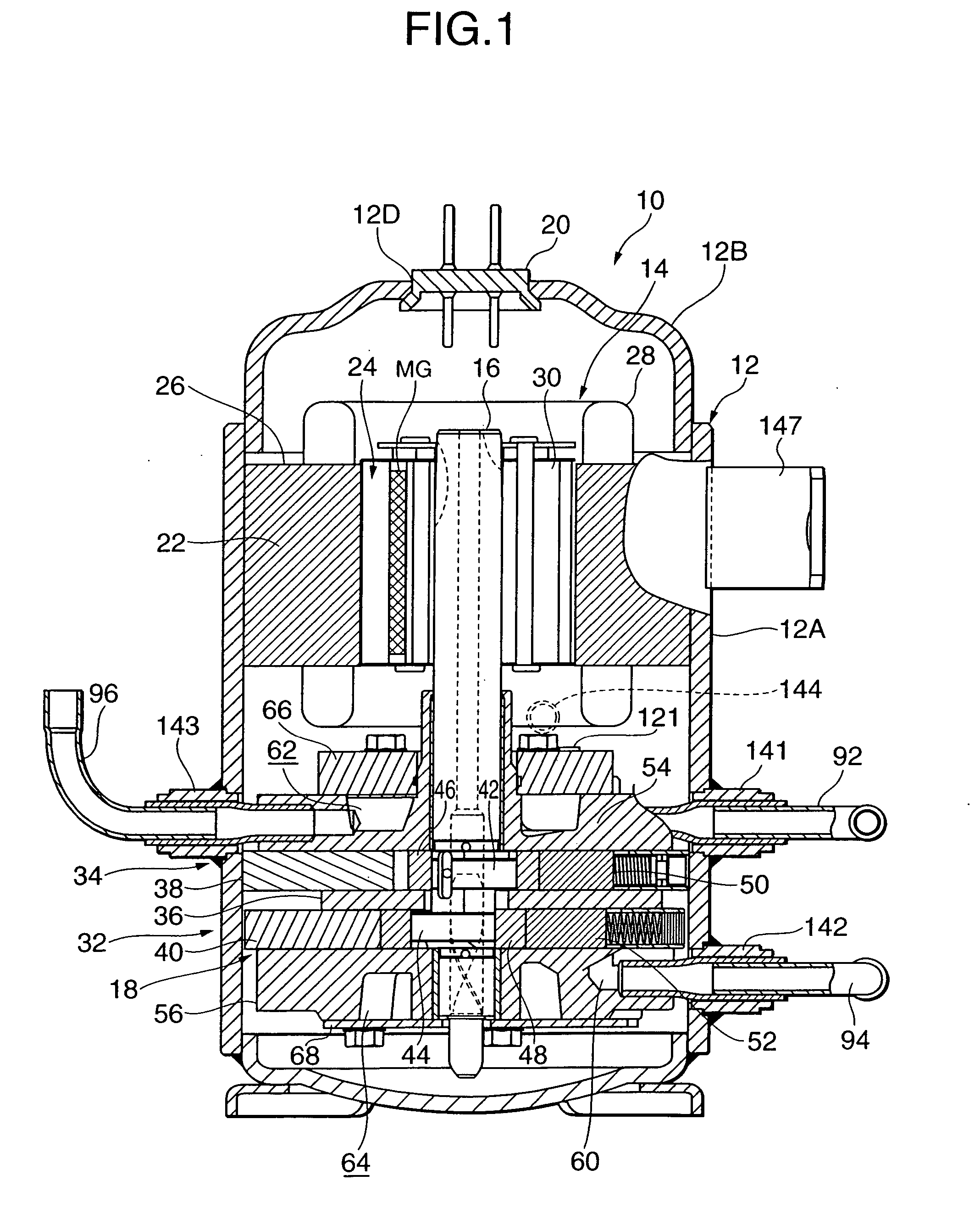
[0024] Next, an embodiment of the present invention will be described in detail with reference to the drawings. FIG. 1 is a longitudinal section of an internal intermediate pressure type multistage (two stage) compression rotary compressor 10 having first and second rotary compression elements as an embodiment of a compressor used in a refrigerant cycle system of the present invention.

[0025] That is, reference numeral 10 denotes an internal intermediate pressure type multistage compression rotary compressor using CO2 (carbon dioxide) as a refrigerant. The compressor 10 comprises a sealed cylindrical vessel 12 which is formed of a steel plate, an electrically driven element 14 which is placed in an upper portion of the inside of the sealed vessel 12, and a rotary compression mechanism 18 comprising a first rotary compression element 32 (first stage) and a second rotary compression element 34 (second stage) which are placed under the electrically driven element 14 and driven by a rot...


PUM


Abstract

An object of the present invention is to improve a heat exchanging capability in an evaporator in a refrigerant cycle system in which a high pressure side is operated at a supercritical pressure. The refrigerant cycle system is a refrigerant cycle system in which a compressor, a gas cooler, an expansion valve and an evaporator are sequentially connected in a cyclic form and a high pressure side is operated at a supercritical pressure, wherein the degree of opening of the expansion valve is adjusted based on the temperature and pressure of a refrigerant at an outlet of the evaporator so as to control the degree of superheat at the outlet of the evaporator. An abstract of the present invention is to make large the degree of superheat at the outlet of the evaporator by means of the expansion valve.

Description

BACKGROUND OF THE INVENTION [0001] (i) Field of the Invention [0002] The present invention relates to a refrigerant cycle system in which a compressor, a gas cooler, throttle means and an evaporator are sequentially connected-in a cyclic form and a high pressure side is operated at a supercritical pressure. [0003] (ii) Description of the Related Art [0004] Heretofore, in an automotive air conditioner for air-conditioning the inside of an automobile, for example, a rotary compressor (compressor), a gas cooler, an intermediate heat exchanger, throttle means (such as an expansion valve), an evaporator and the like are sequentially connected in a cyclic form via pipes so as to constitute a refrigerant cycle (refrigerant circuit). A refrigerant gas is sucked into a low pressure chamber of a cylinder from a suction port of a rotary compression element of the rotary compressor and then compressed by the actions of a roller and a vane so as to become a high temperature / high pressure refrige...

Claims


Application Information

Patent Timeline
Patent Type & Authority Applications(United States)
IPC IPC(8): F25B9/00
CPCF25B9/008F25B2309/061F25B2600/21F25B2600/2513F25B2700/197F25B2700/2104F25B2700/2106F25B2700/21175F25B1/00
Inventor DOI, SHIGETOSHIEBARA, TOSHIYUKIKUROSAWA, YOSHIAKIISHINO, MITSUHIKOFUKUDA, EIJIKOBAYASHI, YOSHIHIKOYOSHIDA, ARITOMO
Owner SANYO ELECTRIC CO LTD
Why Eureka
Try Eureka