Rail anchor isolator

a technology for isolators and rail anchors, which is applied in the direction of tracks, roads, constructions, etc., can solve the problems of concrete tie damage and special problems that aris

Active Publication Date: 2006-12-12
PROGRESS RAIL SERVICES
View PDF4 Cites 23 Cited by
  • Summary
  • Abstract
  • Description
  • Claims
  • Application Information

AI Technical Summary

Benefits of technology

[0006]The present invention provides an isolator particularly adapted for use with a rail anchor utilized in an application where railroad rail is installed on concrete ties. The isolator protects the concrete tie from longitudinal movement of the rail due to expansion and contraction due to changing temperatures, and the acceleration and deceleration of trains.

Problems solved by technology

Special problems have arisen due to the use of concrete ties in certain railroad rail installations.
The particular problem with railroad rail mounted on concrete ties is longitudinal rail movement when holding is provided with resilient fasteners.
However, abrasions from the steel rail anchor against the concrete tie tend to erode and eventually damage the concrete tie.

Method used


Image

  • Rail anchor isolator
  • Rail anchor isolator
  • Rail anchor isolator

Examples


Embodiment Construction

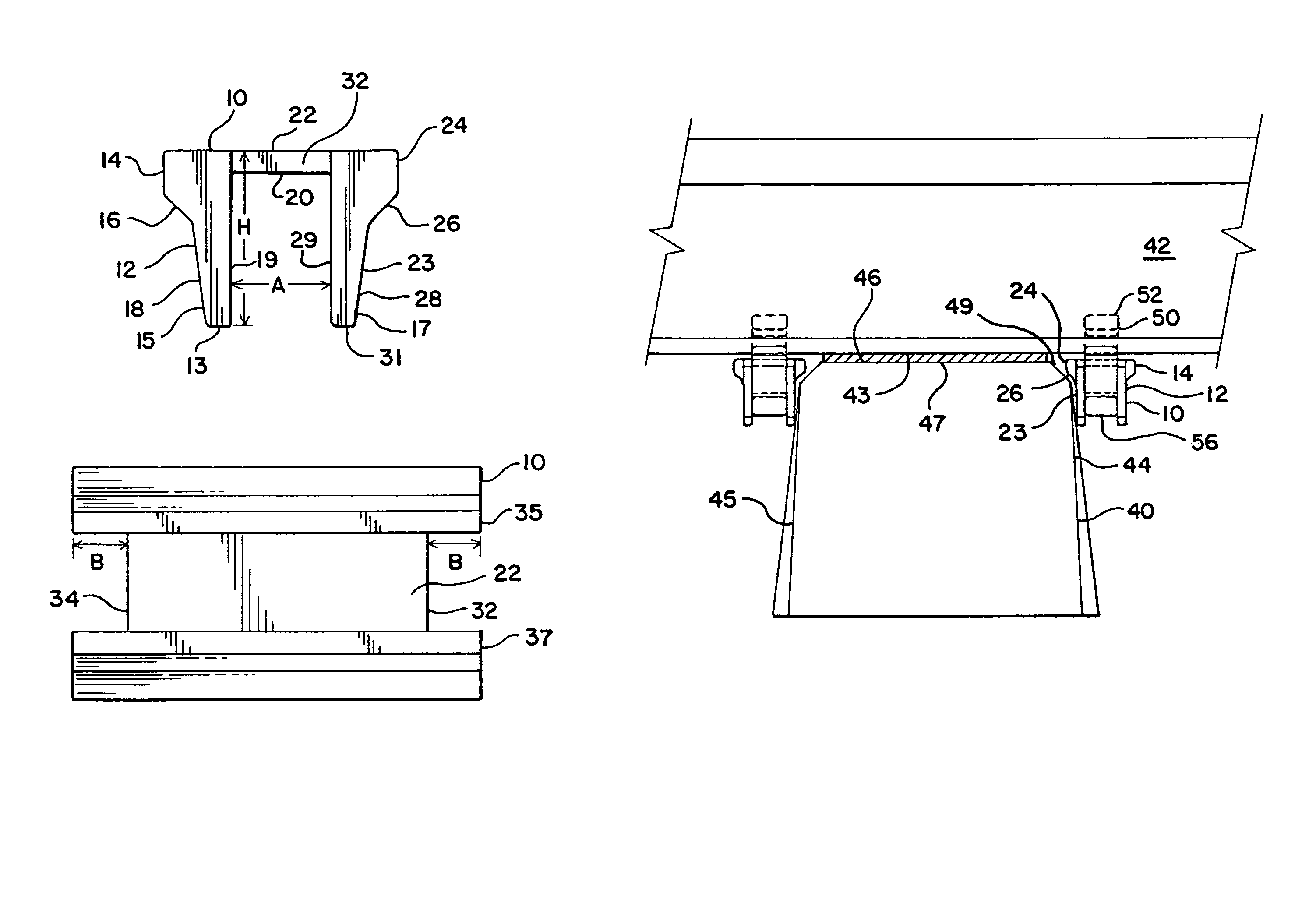
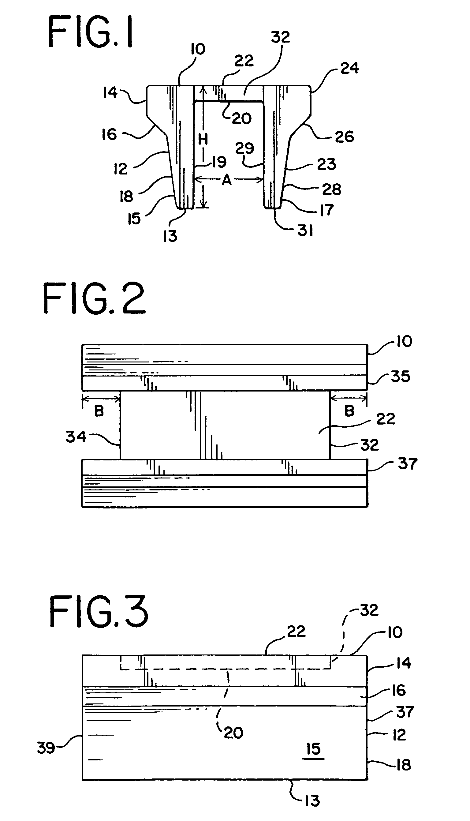
[0022]Referring now to FIGS. 1–3, a rail anchor isolator is shown generally at 10. Rail anchor isolator I0 is seen to be of a general channel shape in cross-section, and is comprised of front face section 12 and rear face section 23. Center section 20 is seen to extend between and join front face section 12 and rear face section 23. The top surface 22 of center section 20 is seen to be planar with the top surfaces of front face section 12 and rear face section 23 to form a generally flat top surface of rail anchor isolator 10.

[0023]Front face section 12 is seen to be a generally elongated, rectangular structure having a top edge, a bottom edge 13, and two side edges 37 and 39. Front face section 12 also includes rib section 14 which extends laterally and includes an angle section 16 that extends from front face section depending lower section 18. Front face section depending lower section 18 is seen to taper to a decreasing thickness toward bottom edge 13.

[0024]Similarly, rear face ...


PUM


Abstract

The present invention provides an isolator particularly adapted for use with a rail anchor utilized in an application where railroad rail is installed on concrete ties. The isolator protects the concrete tie from contact with the rail anchor caused by longitudinal movement of the rail due to train acceleration of deceleration or expansion and contraction due to temperature changes. In one embodiment, the isolator is comprised of a structural plastic material and includes a front face section and a rear face section. The front face section and rear face section each comprise a generally rectangular structure, having a top edge, bottom edge, and side edges. A center section joins the front face section and rear face section and forms part of the top of the isolator. In another embodiment, the front face section includes a top section and bottom section, with the top section having a lower edge projecting laterally at an acute angle from the bottom section. Similarly, the rear face section includes a top section and a bottom section, with the top section having a lower edge projecting laterally at an acute angle from the bottom section.

Description

BACKGROUND OF THE INVENTION[0001]The present invention relates to an isolator for use with a rail anchor and, more particularly, to an isolator for use with a rail anchor applied to railroad rail mounted on concrete ties.[0002]In the installation and operation of railroad rail, the standard rail fastener is a spike driven into a wood tie on either side of the rail. Such arrangement is designed to keep the lateral spacing between rails to maintain gauge distance. Tie plates are also utilized as bearing pads against lateral and vertical forces.[0003]Special problems have arisen due to the use of concrete ties in certain railroad rail installations. One approach to restricting and restraining rail used with concrete ties is shown in U.S. Pat. No. 5,016,816.[0004]The particular problem with railroad rail mounted on concrete ties is longitudinal rail movement when holding is provided with resilient fasteners. Rail anchors can be used to restrict such longitudinal rail movement, which typ...

Claims


Application Information

Patent Timeline
Patent Type & Authority Patents(United States)
IPC IPC(8): E01B9/00
CPCE01B13/02
Inventor WALSH, CASEY
Owner PROGRESS RAIL SERVICES
Why Eureka
Try Eureka