Apparatus and methods for cooling turbine bucket platforms

a bucket platform and bucket technology, applied in mechanical apparatus, blade accessories, machines/engines, etc., can solve the problems of oxidation, creep cracking, and exacerbate the potential distress of bucket platforms, and insufficient pressure to film cool the entire platform

Active Publication Date: 2006-12-12
GENERAL ELECTRIC CO
View PDF8 Cites 47 Cited by
  • Summary
  • Abstract
  • Description
  • Claims
  • Application Information

AI Technical Summary

Problems solved by technology

As gas path temperatures have increased, bucket platforms have increasingly exhibited distress including oxidation, creep and low cycle fatigue cracking.
This exacerbates the potential distress on bucket platforms as they run hotter.
Also, film cooling carryover from upstream nozzle side walls tended to lower the temperatures near the platforms from the resulting “pitch line bias” of the inlet temperature profile.
This is limited to areas where there is sufficient pressure to inject the film, and many current designs have insufficient pressure to film cool the entirety of the platform.

Method used


Image

  • Apparatus and methods for cooling turbine bucket platforms
  • Apparatus and methods for cooling turbine bucket platforms
  • Apparatus and methods for cooling turbine bucket platforms

Examples


Embodiment Construction

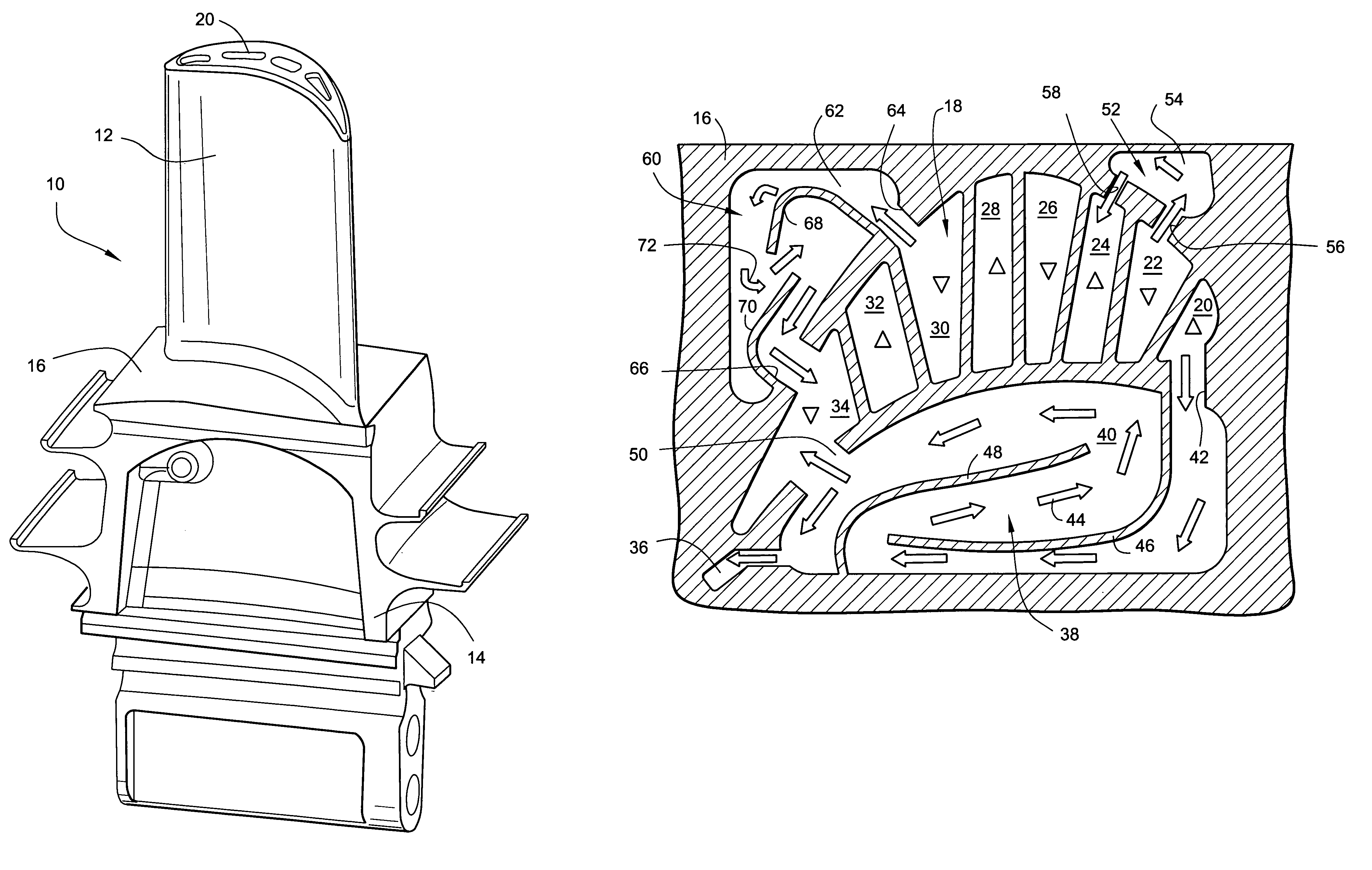
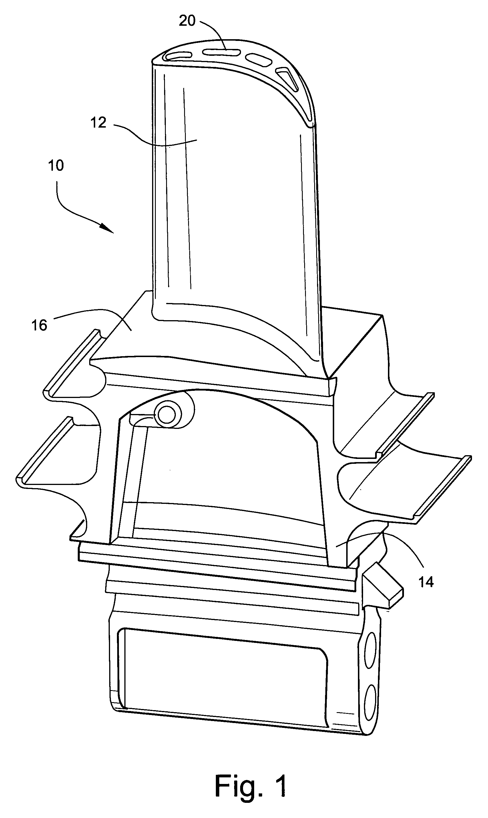
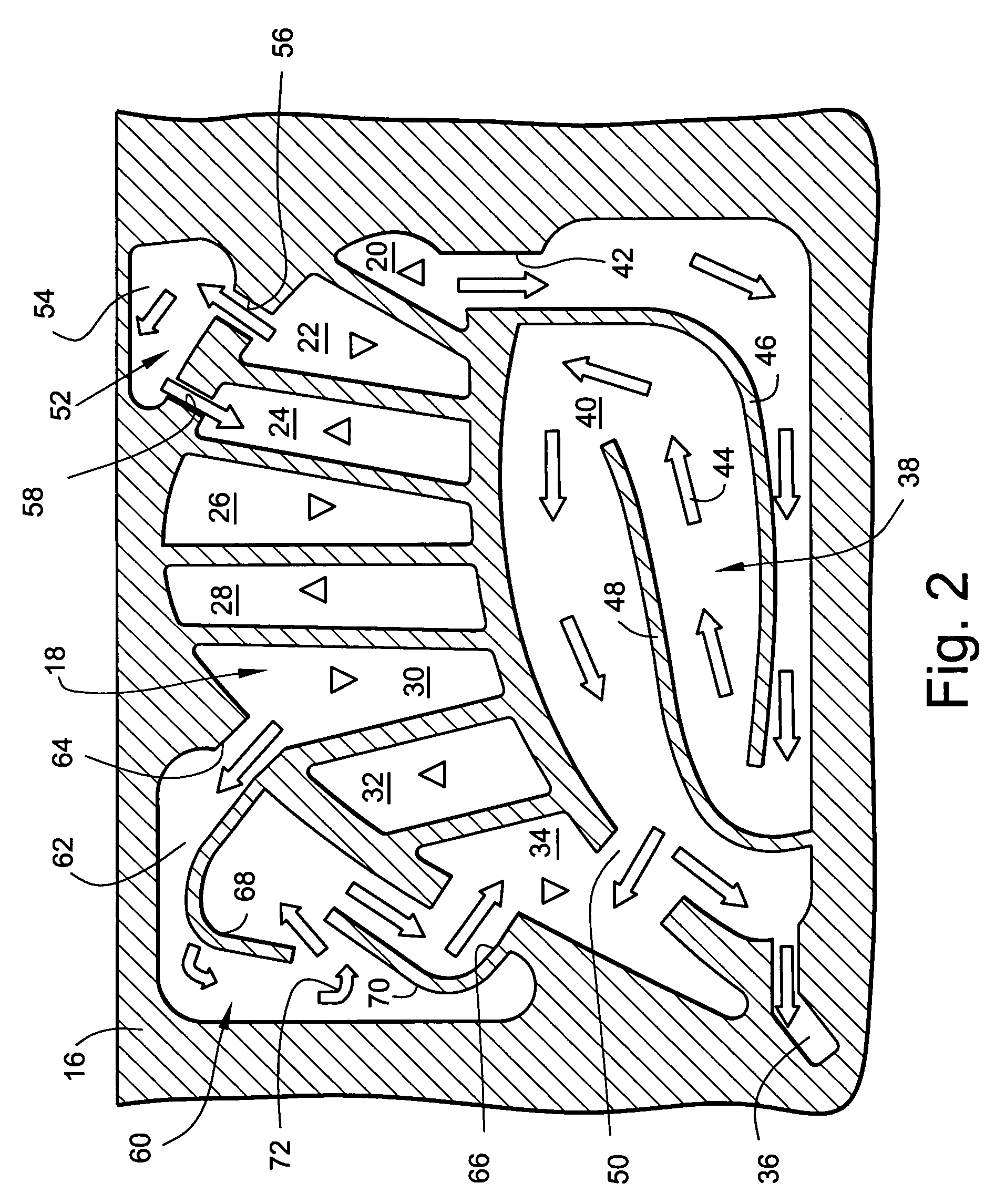
[0009]Referring now to the drawing figures, particularly to FIG. 1, there is illustrated a bucket generally designated 10 for a gas turbine including an airfoil 12 and a bucket root 14. A bucket platform 16 lies at an interface between the airfoil 12 and root 14. The airfoil 12 has a cooling circuit generally designated 18 in FIG. 2 including a plurality of generally radial passages for receiving a cooling medium and flowing the cooling medium along the airfoil 12 to cool the airfoil. It will be appreciated that the cooling medium may constitute steam or air and that any number of cooling passages may be arranged within the airfoil 12. For example, as illustrated in FIG. 2, there are provided eight passages which form the airfoil cooling circuit. The passages may be in the form of a closed circuit, for example, for steam cooling, similarly as set forth in U.S. Pat. No. 5,536,143 of common assignee herewith, or the passages may comprise open circuits with one or more of the passages ...


PUM


Abstract

A bucket has an airfoil, a root and a platform between the root and airfoil. The airfoil includes a serpentine cooling circuit, and the platform includes plural cavities, one or more cavities each having a serpentine cooling circuit. Cooling medium is drawn from one of the passages of the airfoil cooling circuit for flow in the platform cooling circuit and for return either to another passage of the airfoil circuit or to a trailing edge exit. The platform cooling circuits thus convectively cool both high and low pressure sides of the platform.

Description

BACKGROUND OF THE INVENTION[0001]The present invention relates to buckets for turbines and particularly relates to a cooling system for cooling the platforms interfacing between the bucket airfoils and bucket roots.[0002]Over the years, gas turbines have trended towards increased inlet firing temperatures to improve output and engine efficiencies. As gas path temperatures have increased, bucket platforms have increasingly exhibited distress including oxidation, creep and low cycle fatigue cracking. With the advent of closed circuit steam cooling, e.g., in the first two stages of buckets and nozzles in industrial gas turbines, inlet profiles have become such that the platforms are exposed to temperatures close to peak inlet temperatures for the blade row. This exacerbates the potential distress on bucket platforms as they run hotter.[0003]Many older bucket designs did not require active cooling of the platforms due to lower firing temperatures. Also, film cooling carryover from upstr...

Claims


Application Information

Patent Timeline
Patent Type & Authority Patents(United States)
IPC IPC(8): F01D5/18
CPCF01D5/08F01D5/18F01D5/187F01D25/12F05D2240/81F05B2240/801
Inventor JACALA, ARIEL CAESARITZEL, GARY M.
Owner GENERAL ELECTRIC CO
Why Eureka
Try Eureka