Radar apparatus, radar apparatus controlling method

a control method and radar technology, applied in the field of radar techniques, can solve the problems of difficult detection of targets in distance ranges of 100 meters or more, difficulty in detecting targets in extremely short ranges such as approximately 10 centimeters with the same degree of accuracy, and complex configuration, so as to achieve the effect of reducing size and cost, reducing cost, and widening the use range of radar apparatus

Inactive Publication Date: 2006-12-12
FUJITSU LTD +1
View PDF21 Cites 43 Cited by
  • Summary
  • Abstract
  • Description
  • Claims
  • Application Information

AI Technical Summary

Benefits of technology

[0016]An object of the present invention is to provide a radar apparatus that can detect a target in a wide range from a long to short range with one apparatus at low cost.
[0019]According to the present invention, a long- and short-range radar which conventionally requires two long- and short-range radars can be implemented with only one radar. Accordingly, comparing with a configuration using three apparatuses, where long- and short-range radars, which are managed by one more integrated apparatus, a size and cost are reduced to one third. As a result, a radar apparatus which can detect a target in a wide range from a long to short range at low cost can be provided, and there is an effect that a use range of the radar apparatus is significantly widened.

Problems solved by technology

A conventional FM-CW (Frequency Modulation-Continuous Wave) radar system can detect a target in a distance range of several meters to a hundred and several tens of meters, but has a difficulty in the detection of a target in an extremely short range such as approximately 10 centimeters with the same degree of accuracy.
In the meantime, an ultra-short pulse radar system can detect a target in a distance range of approximately 10 centimeters to a ten and several meters with high accuracy, but has a difficulty in the detection of a target in a distance range of 100 meters or more.
Such a system has a disadvantage that its configuration becomes complex, and its cost becomes expensive in comparison with a case where a detection system is implemented with one apparatus.
Therefore, the radar transmitter / receiver disclosed by Patent Document 1 is inconsistent with the common knowledge of techniques in this field.
Namely, for the FM-CW radar, if a detection distance is very short such as 1 meter or less, a beat frequency obtained from transmission and reception signal becomes very low, and it becomes difficult to accurately count the frequency.
Additionally, it is difficult to discriminate the two targets that approach in a range of several tens of centimeters.
However, it is very difficult to manufacture the linear FM modulator which has low modulation distortion with the frequency deviation of 750 MHz, and an FM oscillator for implementing this FM modulation becomes very expensive.

Method used


Image

  • Radar apparatus, radar apparatus controlling method
  • Radar apparatus, radar apparatus controlling method
  • Radar apparatus, radar apparatus controlling method

Examples


Embodiment Construction

[0034]Preferred embodiments according to the present invention are described in detail below with reference to the drawings.

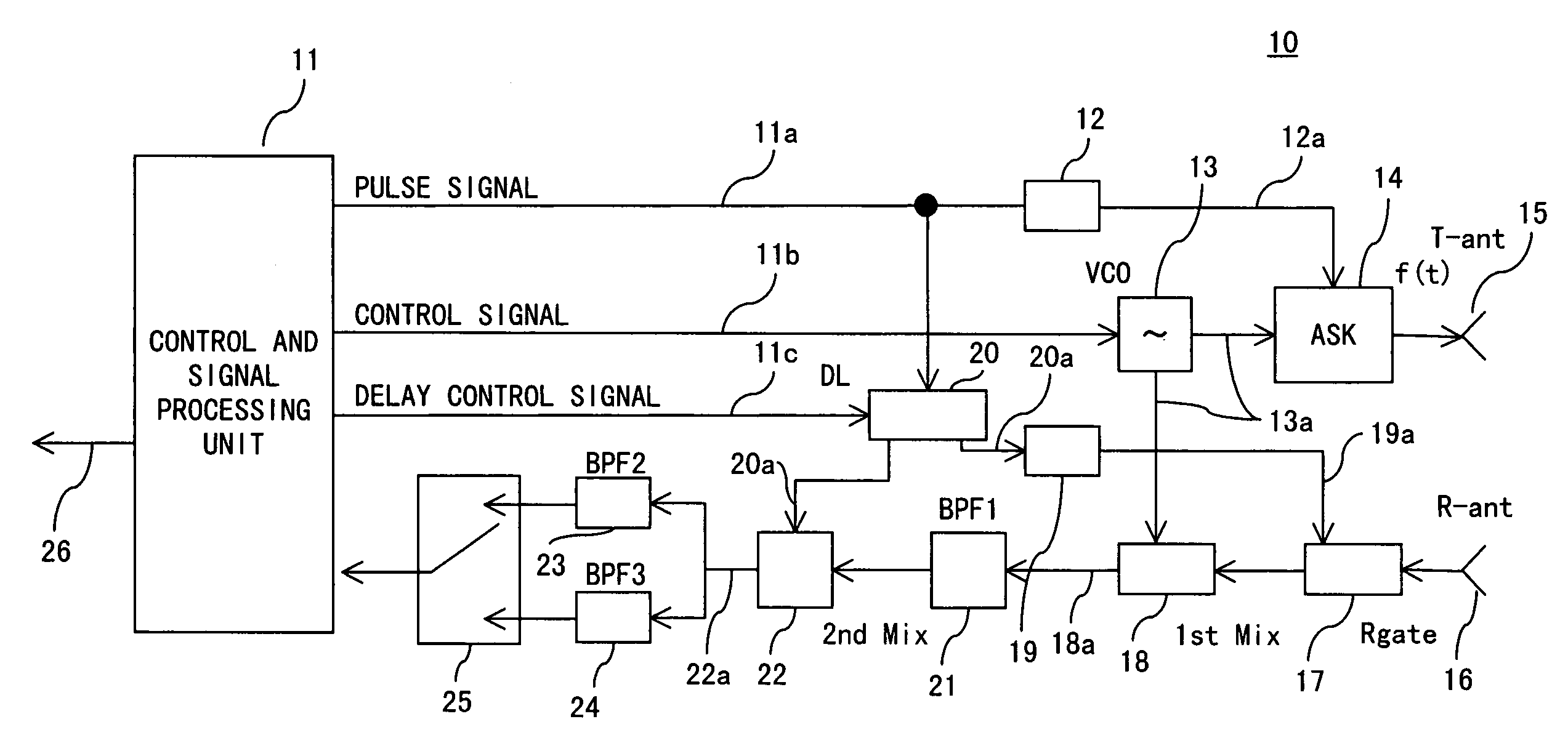
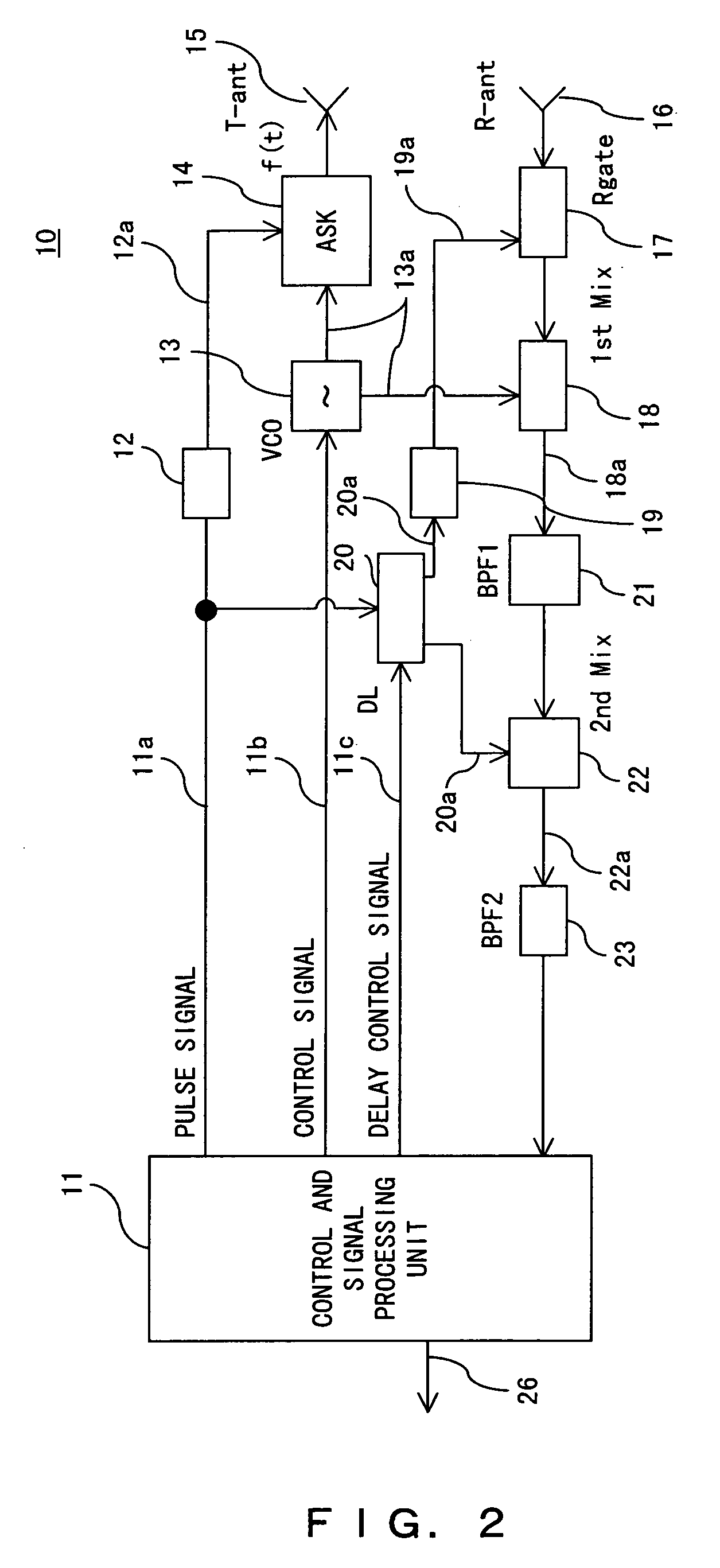
[0035]FIG. 2 is a block diagram exemplifying a configuration of a radar apparatus according to a preferred embodiment of the present invention. FIGS. 3 to 6 are schematics exemplifying an action of the radar apparatus.

[0036]The radar apparatus according to this preferred embodiment comprises: a transmitting unit having a transmitter high-frequency FM modulation oscillator 13, a transmitter high-frequency ASK switching circuit 14, a short pulse generation circuit 12, and a transmitter antenna 15; a receiving unit having a receiving antenna 16, a receiver high-frequency gate circuit 17, a first mixer 18 (first frequency converter), a short pulse generation circuit 19, a programmable delay circuit 20, a band-pass filter 21 (first band-pass filter), a second mixer 22 (second frequency converter), and a band-pass filter 23 of a beat frequency band (second band-pass ...


PUM


Abstract

A radar apparatus comprises: a transmitter unit having a high-frequency oscillating unit whose oscillation frequency is variable, and a pulse amplitude modulating unit for amplitude-modulating a pulse of a transmission high-frequency signal output from the high-frequency oscillating unit with a first control pulse signal; a receiver unit having a gating unit for controlling ON / OFF of an input of a received high-frequency signal with a second control pulse signal; and a controlling and signal processing unit for controlling the transmitter unit and the receiver unit, and for switching a first operation mode for making the apparatus function as an FM-CW radar, and a second operation mode for making the apparatus function as a pulse radar.

Description

BACKGROUND OF THE INVENTION[0001]1. Field of the Invention[0002]The present invention relates to a radar technique, and more particularly, to an effective technique being applied to detect a target positioned in a wide range from a long to short range.[0003]2. Description of the Related Art[0004]Attention is paid to a millimeter wave radar technique intended to observe, for example, an obstruction on a road, and a traffic condition in operation management the car with the radar.[0005]A conventional FM-CW (Frequency Modulation-Continuous Wave) radar system can detect a target in a distance range of several meters to a hundred and several tens of meters, but has a difficulty in the detection of a target in an extremely short range such as approximately 10 centimeters with the same degree of accuracy. In the meantime, an ultra-short pulse radar system can detect a target in a distance range of approximately 10 centimeters to a ten and several meters with high accuracy, but has a diffic...

Claims


Application Information

Patent Timeline
Patent Type & Authority Patents(United States)
IPC IPC(8): G01S13/38G01S13/10G01S13/32G01S13/93G01S13/931
CPCG01S7/02G01S13/08G01S13/582G01S13/87G01S13/931G01S2013/9375G01S2013/9378G01S2013/9321G01S2013/93272G01S2013/93271G01S13/34
Inventor DOOI, YOSHIKAZUISHII, SATOSHIYATSUKA, HIROYUKISHIMA, NOBUKAZUHITOTSUYA, MASAKI
Owner FUJITSU LTD
Why Eureka
Try Eureka