Electro-dynamic loudspeaker mounting system

a technology of mounting system and loudspeaker, which is applied in the direction of machine supports, transportation and packaging, and other domestic objects, can solve the problems of not being able to position or orient the desired loudspeaker, and using a loudspeaker, etc., and achieve the desired performance of the audio system

a technology of mounting system and loudspeaker, which is applied in the direction of machine supports, transportation and packaging, and other domestic objects, can solve the problems of not being able to position or orient the desired loudspeaker, and using a loudspeaker, etc., and achieve the desired performance of the audio system

US7149321B2Active Publication Date: 2006-12-12HARMAN INT IND INC

Image

  • Electro-dynamic loudspeaker mounting system
  • Electro-dynamic loudspeaker mounting system
  • Electro-dynamic loudspeaker mounting system

Examples


Embodiment Construction

[0040]An electro-dynamic planar loudspeaker 100 may be mounted in a vehicle, for example, an automobile, by the mounting brackets. The mounting apparatus may be adapted to mount and secure any of a variety of components or sub-assemblies in any of a variety of desired locations in the vehicle.

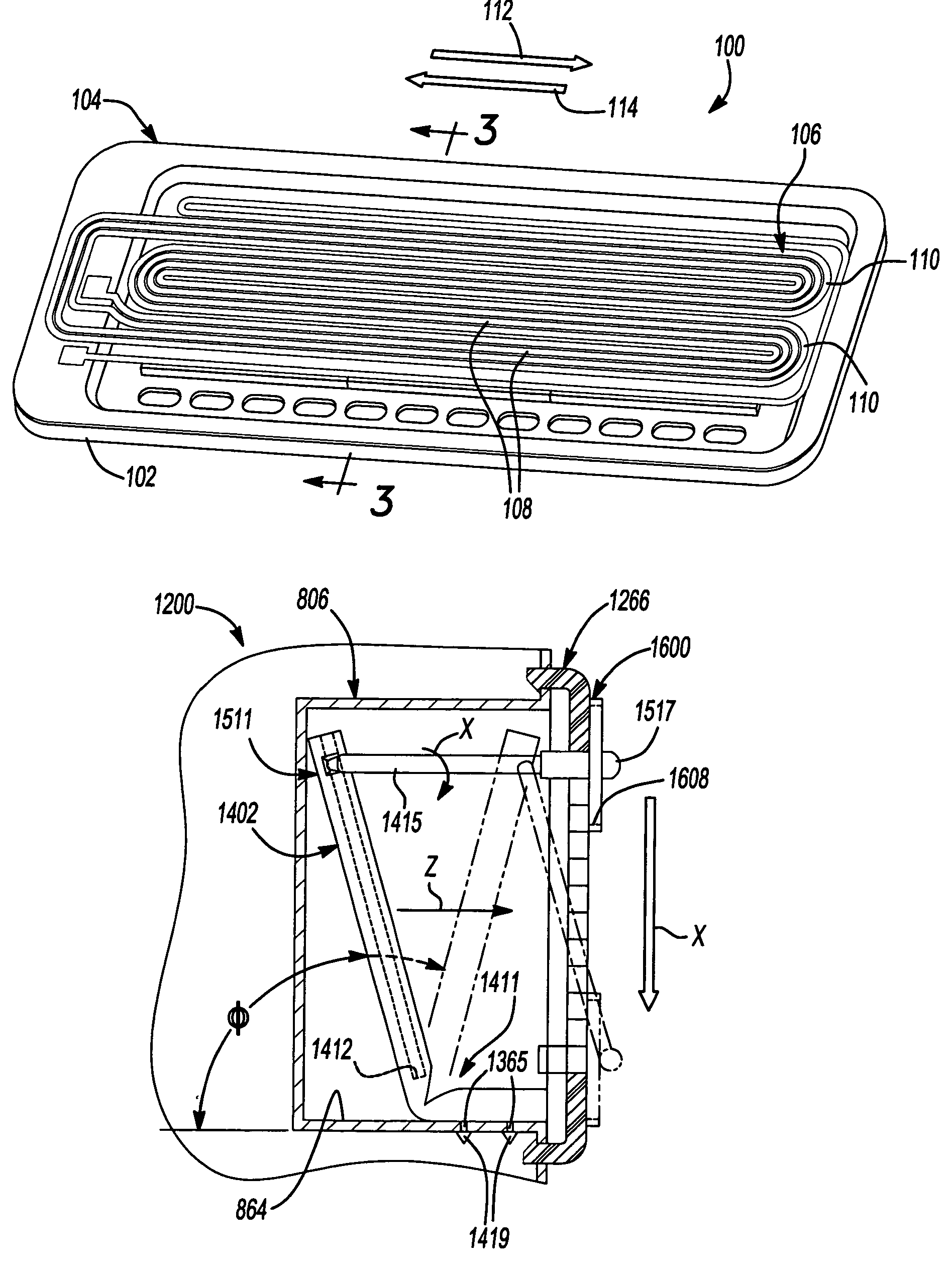
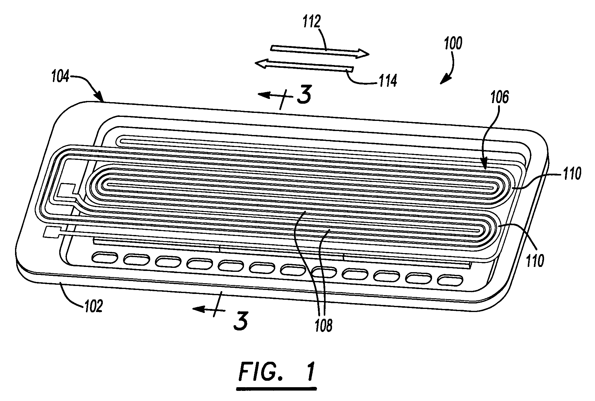
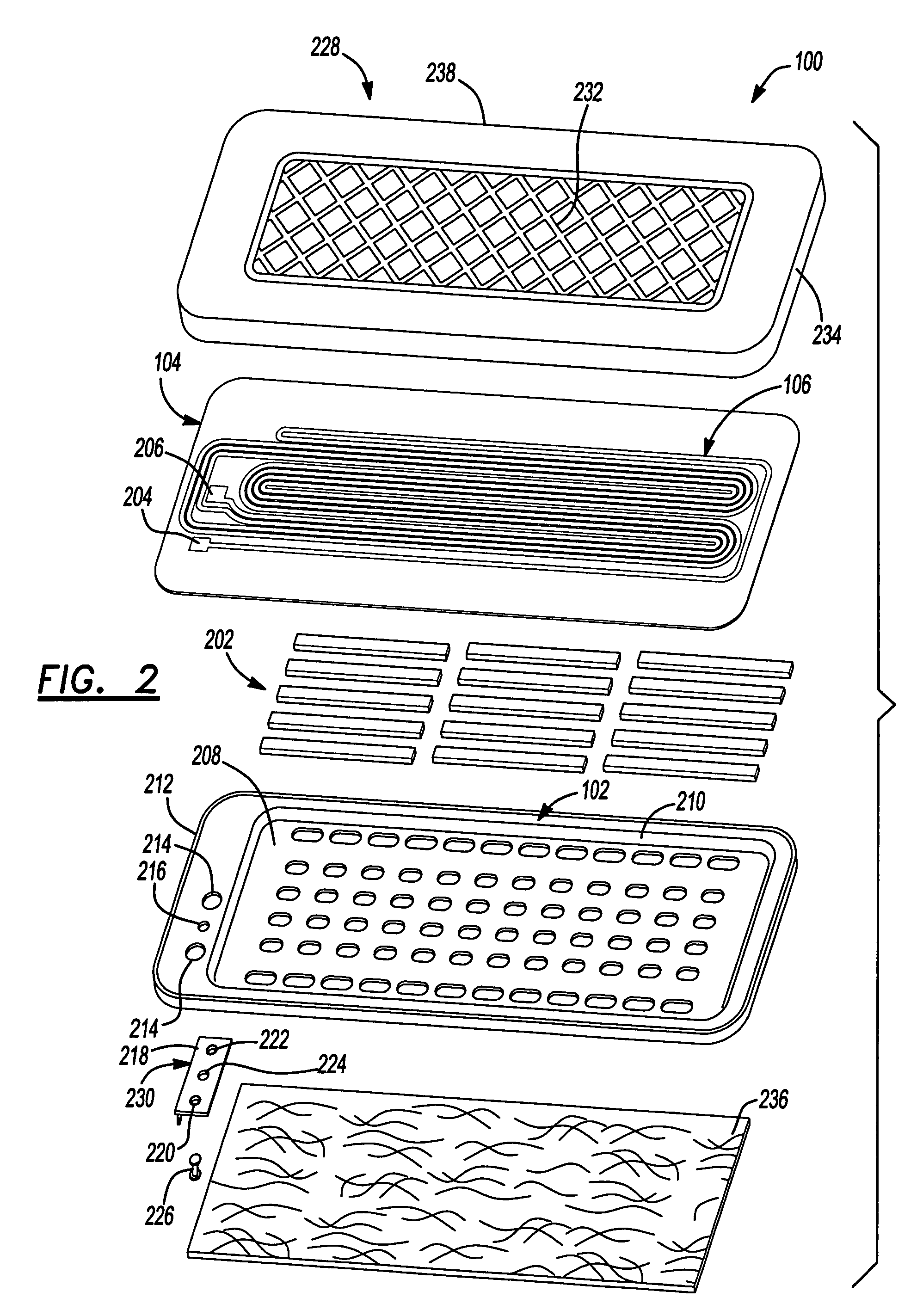
[0041]FIG. 1 is a perspective view of an electro-dynamic loudspeaker 100 of the invention. As shown in FIG. 1, the electro-dynamic loudspeaker is a generally planar loudspeaker having a frame 102 with a diaphragm 104 attached in tension to the frame 102. A conductor 106 is positioned on the diaphragm 104. The conductor 106 is shaped in serpentine fashion having a plurality of substantially linear sections (or traces) 108 longitudinally extending along the diaphragm interconnected by radii 110 to form a single current path. Permanent magnets 202 (shown in FIG. 2) are positioned on the frame 102 underneath the diaphragm 104, creating a magnetic field.

[0042]Linear sections 108 are positioned withi...


PUM


Abstract

A mounting apparatus for attaching a device like an electro-dynamic loudspeaker to a mounting location in an automobile or other vehicle. The mounting apparatus employs bracket hardware that is either affixed to or integral with the loudspeaker that is to be mounted. The mounting apparatus can position the loudspeaker in a fixed angular orientation, or enable the angular orientation of the loudspeaker to be variable, as desired, to achieve the optimum performance of the loudspeaker.

Description

CROSS-REFERENCE TO RELATED APPLICATIONS[0001]This application claims the benefit of U.S. Provisional Application No. 60 / 380,001, filed on May 2, 2002; U.S. Provisional Application No. 60 / 378,188, filed on May 6, 2002; and U.S. Provisional Application No. 60 / 391,134, filed on Jun. 24, 2002. The disclosures of these patent applications are incorporated by reference.[0002]This application incorporates by reference the disclosures of each of the following co-pending applications which have been filed concurrently with this application: U.S. patent application Ser. No. 10 / 428,313, entitled “Mounting Bracket System,” filed May 2, 2003; U.S. patent application Ser. No. 10 / 429,165, entitled “Film Tensioning System,” filed May 2, 2003; U.S. patent application Ser. No. 10 / 428,316, entitled “Film Attaching System,” filed May 2, 2003; U.S. patent application Ser. No. 10 / 429,228, entitled “Electrical Connectors For Electro-Dynamic Loudspeakers,” filed May 2, 2003; U.S. patent application Ser. No...

Claims


Application Information

Patent Timeline
12 Dec 2006
Publication
US7149321B2
IPC
H04B1/00; H04R1/02; B60R11/02; H04R1/06; H04R5/02; H04R7/04; H04R7/18; H04R9/02; H04R31/00
CPC
B60R11/0223; H04R1/06; H04R5/02; H04R7/04; H04R7/18; H04R9/025; H04R31/006; H04R2499/13
Inventors
HUTT, STEVEN W.; HOUSE, WILLIAM NEAL