Turret for machine tool

a technology for machine tools and turrets, which is applied in the field of turrets, can solve the problems of reducing the power transmission efficiency of the power transmission mechanism, generating noise, and reducing the power transmission efficiency, and achieves the effect of high accuracy of assembly

Active Publication Date: 2006-12-19
DMG MORI CO LTD
View PDF13 Cites 10 Cited by
  • Summary
  • Abstract
  • Description
  • Claims
  • Application Information

AI Technical Summary

Benefits of technology

[0010]It is an object of the present invention to provide a turret, for use on a machine tool, in which a drive motor can be highly accurately assembled onto a turret body through an opening, of a turret body, which provides easy access to the turret body.
[0023]With the turret arranged as described above, the drive motor can be highly accurately assembled onto the turret body through the opening, of the turret body, which provides easy access to the turret body.

Problems solved by technology

Consequently, the power transmitting mechanism for transmitting the drive power from the drive motor to the rotating tool is relatively complex in structure.
When the power transmitting mechanism is in operation, the belt, bevel gears, and bearings of the power transmitting mechanism generate heat and vibration.
As a result, the power transmitting mechanism causes an energy loss, tending to lower the power transmitting efficiency and generate noise.
According to the tool turret revealed in Published U.S. patent application No. 2004 / 0103510, it is difficult to highly accurately assemble the drive motor onto a turret body through an opening, of the turret body, which provides easy access to the turret body.
As a result, the coupling mechanism is of a complex structure, and it takes time for the coupling mechanism to connect and disconnect the drive motor and the rotating tool.

Method used


Image

  • Turret for machine tool
  • Turret for machine tool
  • Turret for machine tool

Examples


Embodiment Construction

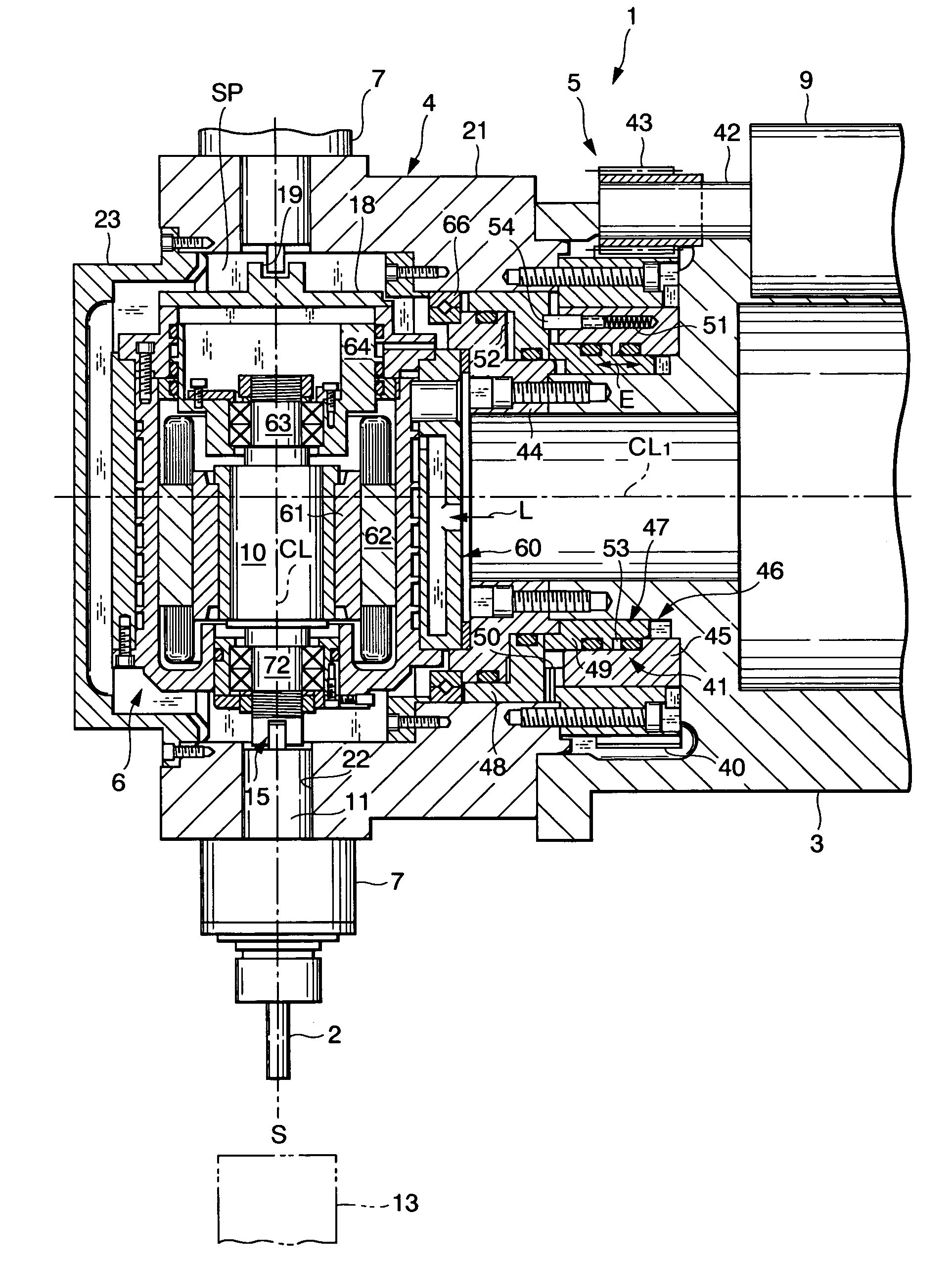
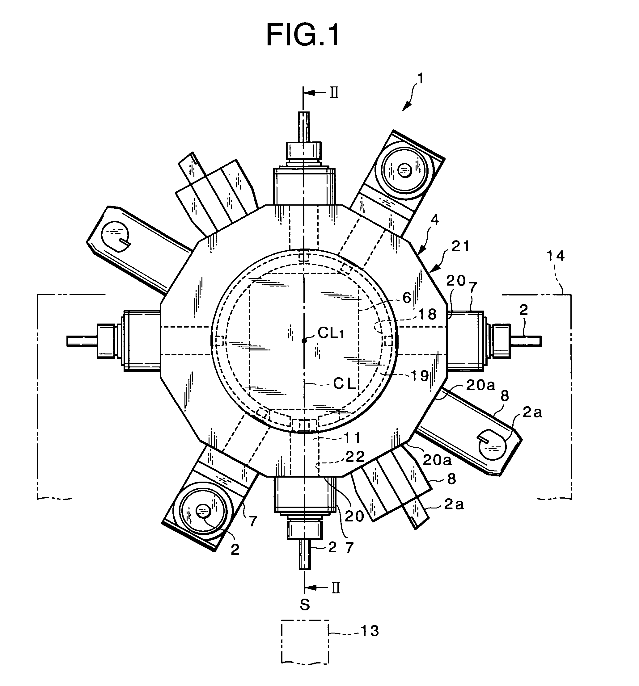
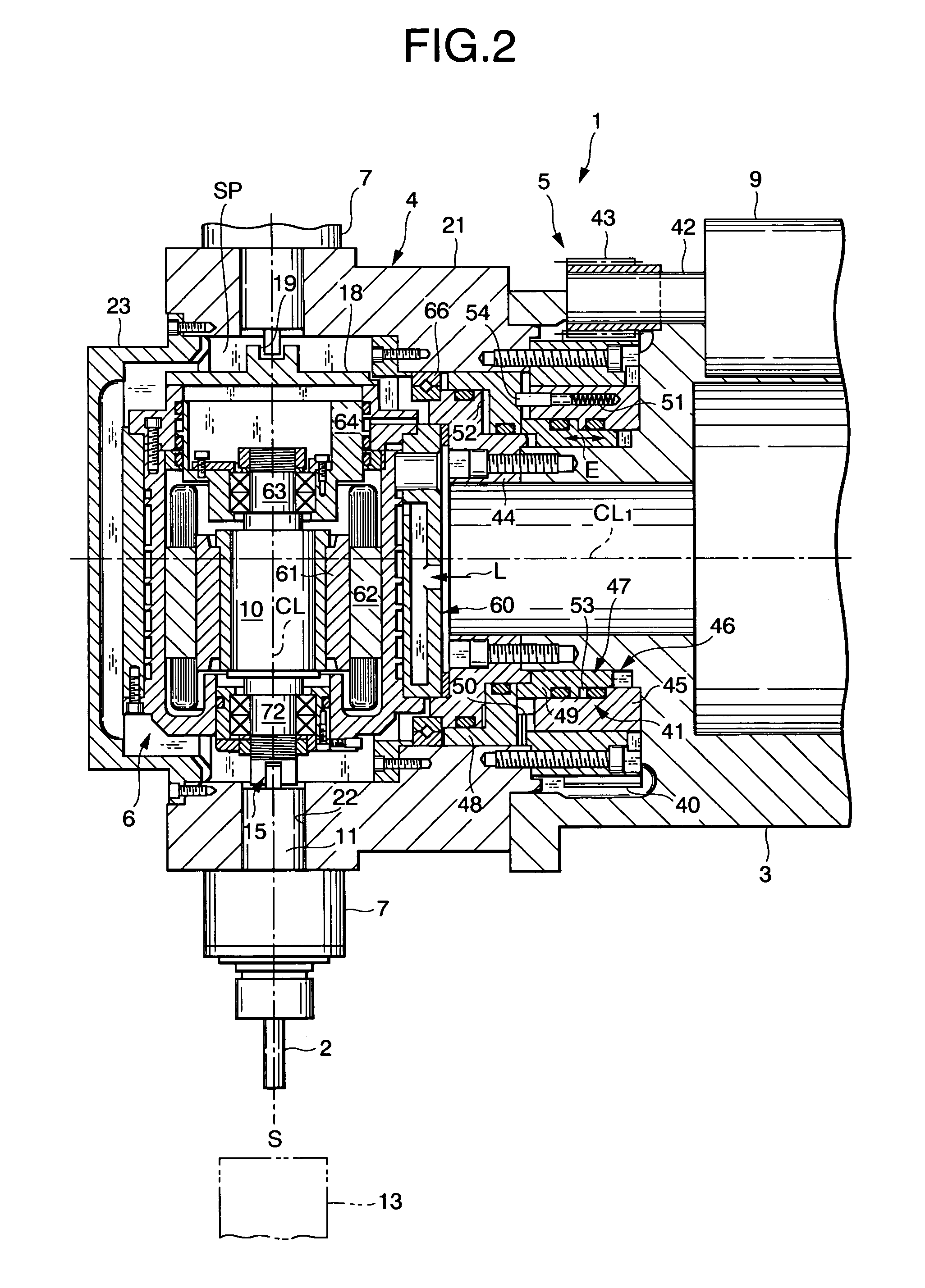
[0028]A turret for a machine tool according to an embodiment of the present invention has a joint directly connecting a rotating tool on a swivel drum and a drive motor to each other while the rotating tool is indexed to an indexed position (machining position). The rotating tool can be rotated about its own axis by the drive motor through the joint.

[0029]The drive motor is fixed to a turret body and the drive motor has a housing supported on the turret body. The turret further comprises a liner whose thickness is adjustable disposed immediately behind the housing. The liner has the thickness thereof adjusted to adjust a position of the drive motor with respect to the turret body. Accordingly, the drive motor can be highly accurately assembled onto the turret body through the opening, of the turret body, which provides easy access to the turret body.

[0030]The joint comprises a protrusion, which is disposed on either one of a holder shaft of a tool holder which holds the rotating too...


PUM

PropertyMeasurementUnit
thicknessaaaaaaaaaa
movementaaaaaaaaaa
diameteraaaaaaaaaa

Abstract

A turret for use on a machine tool has a turret body, a swivel drum, an indexing actuator, a drive motor and a joint. While one of rotating tools on the turret is indexed to an indexed position, the joint directly connects the rotating tool to the drive shaft of the drive motor to rotate the rotating tool with the drive motor. The drive motor is fixed to the turret body and the drive motor has a housing supported on the turret body. The turret further comprises a liner whose thickness is adjustable disposed immediately behind the housing. The liner has the thickness thereof adjusted to adjust a position of the drive motor with respect to the turret body. The drive motor can be highly accurately assembled onto the turret body through an opening, of the turret body, which provides easy access to the turret body.

Description

BACKGROUND OF THE INVENTION[0001]1. Field of the Invention[0002]The present invention relates to a turret, for use on a machine tool, for mounting at least one rotating tool thereon and for rotating the rotating tool to machine a workpiece on the machine tool.[0003]2. Description of the Related Art[0004]Some machine tools, e.g., lathes, have a turret for mounting one or more rotating tools thereon and for rotating them with a drive motor to machine a workpiece on the machine tool. In the lathe, the turret has a swivel block mounted on a head thereof, and a plurality of tools including rotating tools and other machining tools are radially supported on the swivel block.[0005]When the swivel block is swiveled about its own axis, a desired one of the supported tools (e.g., a rotating tool) is indexed to an indexed position (machining position). Then, the drive motor is energized to rotate the rotating tool about its own axis to machine the workpiece. The drive power or torque of the dri...

Claims


Application Information

Patent Timeline
Patent Type & Authority Patents(United States)
IPC IPC(8): B23P23/02B23B29/32
CPCB23Q39/02B23Q2220/002Y10T29/5154Y10T74/14Y10T408/37Y10T29/5155
Inventor ISHIGURO, HARUKI
Owner DMG MORI CO LTD
Why Eureka
Try Eureka