Partition system

a technology of partition system and partition plate, which is applied in the direction of girders, door/window protective devices, variable height tables, etc., can solve the problems of limiting the locational positioning of tiles, affecting the installation effect, so as to achieve convenient movement

Inactive Publication Date: 2006-12-19
KIMBALL INTERNATIONAL
View PDF86 Cites 78 Cited by
  • Summary
  • Abstract
  • Description
  • Claims
  • Application Information

AI Technical Summary

Benefits of technology

[0013]The track members are attached to adjacent pairs of upper sub-frame members or to adjacent pairs of mid-channel members in a fastenerless manner, in which the track members are hung over edge portions of the upper sub-frame members and the mid-channel members. Thus, the track members are easily attachable to the framework without the use of fasteners or tools, such that the configuration of track members upon the framework, and in turn, the configuration of the tiles which are supported upon the framework by the track members, may be easily varied to suit the requirements of users of the partition system. Further, the track members each include anti-dislodgement structure cooperating with the upper sub-frame members and the mid-channel members.
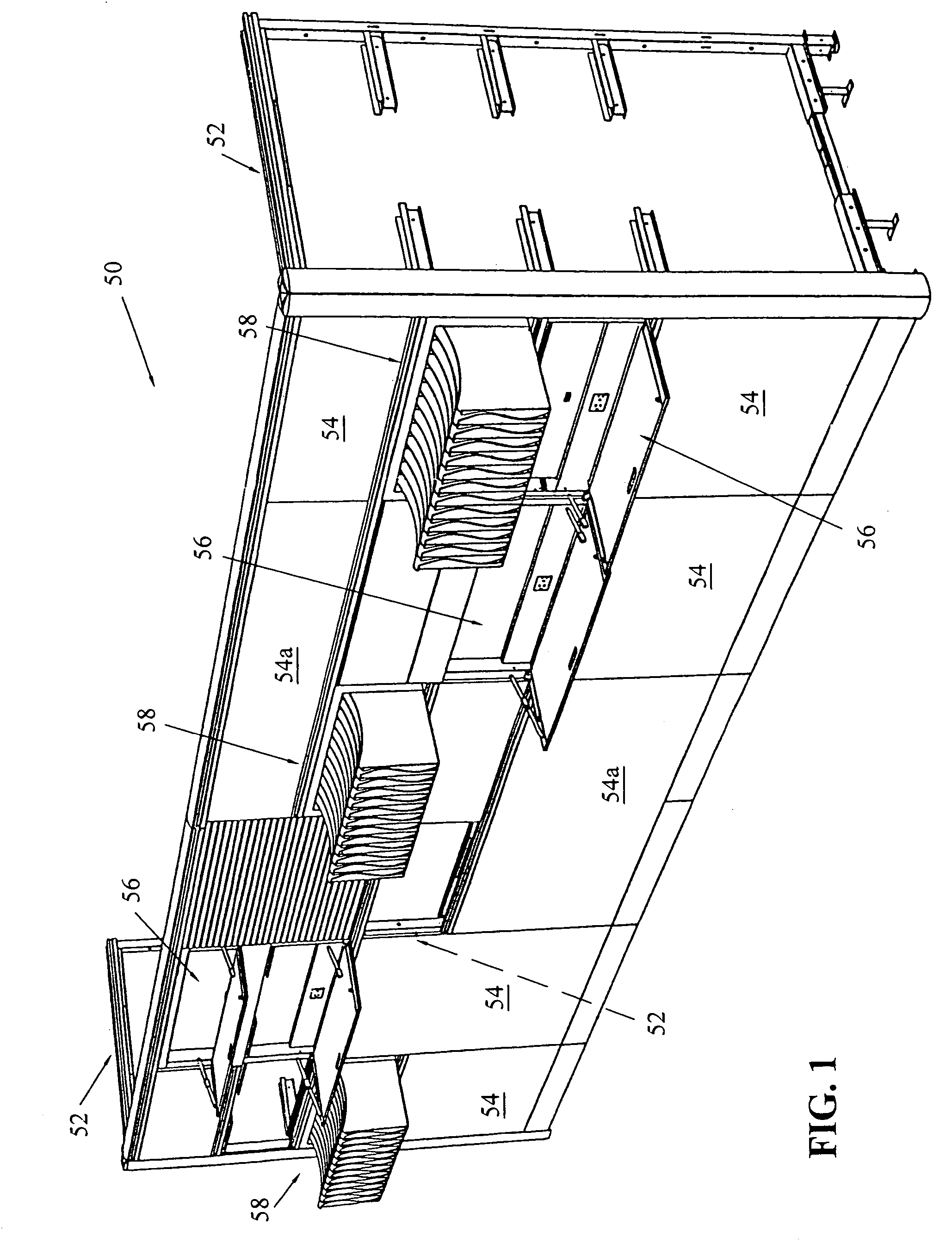
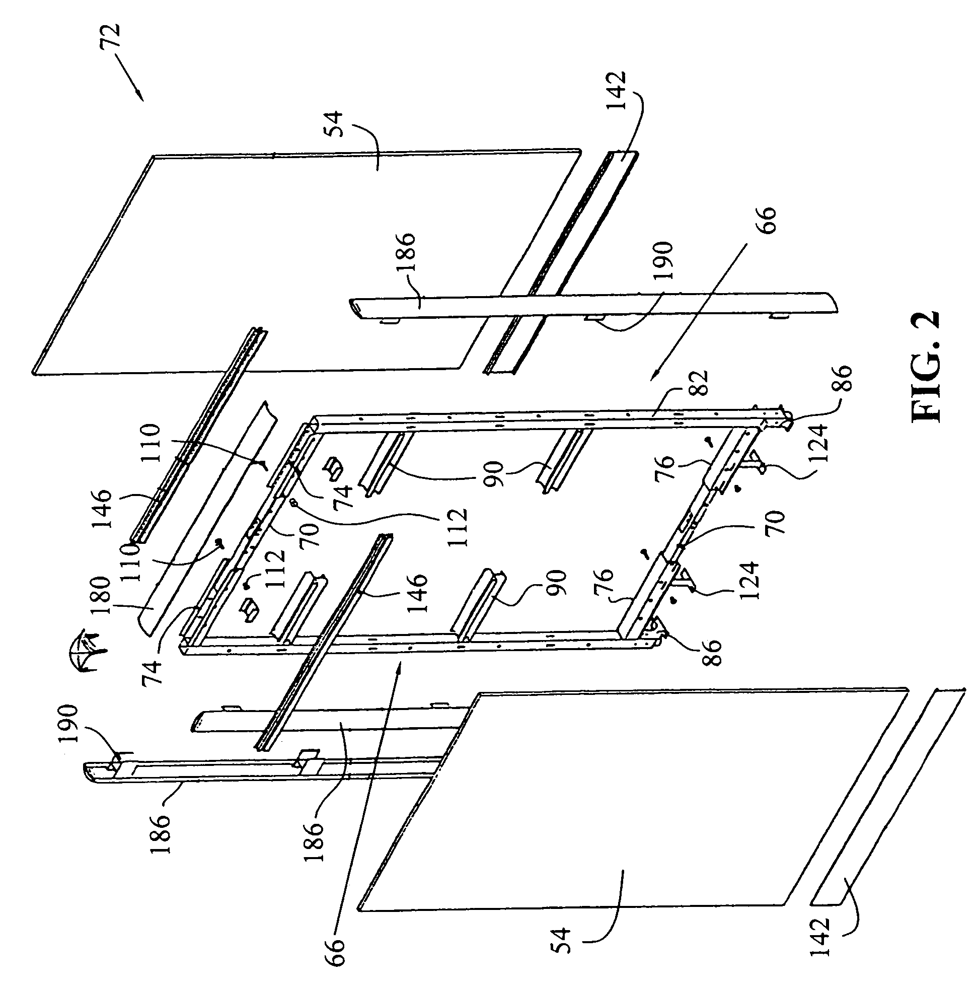
[0017]Additionally, a variety of decorative and functional tiles are provided for attaching to the partition system framework. The decorative tiles may include any exterior facing such as fabric, vinyl, metal, or a functional surface such as a marker board, chalk board, projection screen or a tack board, for example. Functional tiles may include retractable work station tiles and a variety of different types of storage tiles for storing papers and other materials used within an office environment. The decorative and functional tiles are mounted to the framework without the use of tools, such that the particular arrangement of functional and / or decorative tiles on the partition system framework may be easily reconfigured to suit the particular needs of workers within the office space. Additionally, the storage tiles provide storage space within the interior of the partition system framework, in contrast with existing systems, in which the space within the interior of the partition system framework is occupied by filler material or is not used at all.
[0018]Also, a file pocket is provided which is sized to hold standard sized paper, or other office supplies. The file pocket is further dimensioned to be received within a standard sized drawer of a filing cabinet. The file pocket may also be received within the storage cavity or retractable storage bin of a storage tile of the partition system. Further, the file pocket includes hooks for mounting the file pocket to a track member of the partition system. In this manner, the file pocket provides a portable storage component which may be conveniently be moved between known casegoods, such as a filing cabinet, and the present partition system.

Problems solved by technology

Therefore, in order to provide rigid, durable connections between the panel frames, a plurality of brackets, latches, or other structures are needed, which may be difficult and tedious to install.
The decorative tiles are sized to have a width which is co-extensive with the rectangular frames, which disadvatageously limits the locational positioning of the tiles on the frames and does not allow for flexibility in the configuration of the tiles relative to the frames.
Thus, the modular furniture components are disposed in a fixed position relative to the panels and are not easily movable or reconfigurable with respect thereto.
Existing partition systems are substantially fixed after their initial installation, and do not permit easy reconfiguration thereof based upon changing space demands in a workspace.
Existing systems further do not permit easy expansion, in which additional partition systems components are added to partition system components which are already installed.

Method used


Image

  • Partition system
  • Partition system
  • Partition system

Examples


second embodiment

[0134]Referring to FIGS. 24a and 24b, the second embodiment includes corner blocks 220, which are used to connect up to four C-shaped vertical frame members to one another to provide L-, T-, and X-junctions within framework 52. Corner blocks 220 may be formed of a single metal extrusion, for example, or may alternatively be formed from a series of metal pieces attached to one another. Corner blocks 220 generally include central portion 222, and four outwardly-opening channels 224 terminating in upright abutment flanges 226. Attachment tubes 228 are pivotally mounted within channels 224 upon pins 230 which are received through transverse bores 232 of attachment tubes 228 and through the walls of channels 224. Referring to FIG. 24b, each attachment tube 228 additionally includes a longitudinal, threaded bore 234 extending therein opposite the ends of attachment tubes 228 which are attached to channels 224. Referring to FIG. 24a, each attachment tube 228 is pivotable between a retracte...

first embodiment

[0142]Referring to FIGS. 35 and 36, portable storage components, namely horizontal file pocket 276 and vertical file pocket 278 are shown, which each body portions defined by front wall 280a, 280b rear wall 282a, 282b, side walls 284a, 284b, and bottom walls 286 defining storage spaces 288a, 288b, respectively. Storage spaces 288a, 288b may be used to hold papers or office supplies, for example. Front and rear walls 280a, 280b include apertures 290 therein defining handles 292, and also include hooks 294 at the opposite upper ends thereof.

[0143]As shown in FIG. 37, horizontal and vertical file pockets 276 and 278 may be mounted within storage tile 270 by engaging hooks 294 thereof within apertures 296 in rear wall 298 of tile body portion 272 of storage tile 270, wherein bottom walls 286 of horizontal and vertical file pockets 276 and 278 rest against bottom wall 300 of tile body portion 272 of storage tile 270. In FIG. 38, a horizontal series of horizontal file pockets 276 are sho...


PUM


Abstract

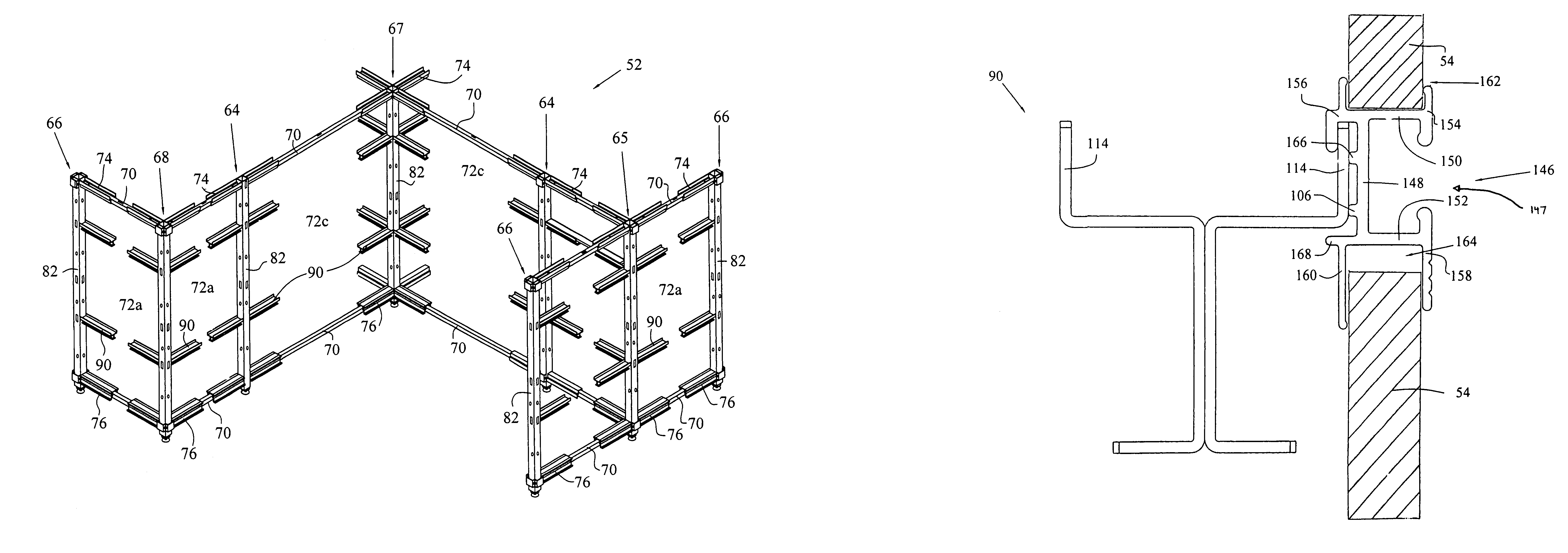
A partition system for office spaces generally includes a framework and a plurality of different types of decorative and / or functional tiles mountable to the framework. The framework includes I- and C-shaped vertical frame members which are adjustably joined by upper and lower horizontal spanners such that the distance between the vertical frame members is adjustable. Also, the framework may include other types of vertical frame members for forming L-, T-, or X-junctions within the partition system framework. A variety of decorative and functional tiles are mountable to the framework, including retractable workspace tiles, several types of storage tiles, display tiles, window tiles, and electrical and data services tiles.

Description

CROSS REFERENCE TO RELATED APPLICATIONS[0001]This application claims the benefit under Title 35, U.S.C. § 119(e) of U.S. Provisional Patent Application Ser. No. 60 / 386,775, entitled PARTITION SYSTEM, filed on Jun. 6, 2002, as well as U.S. Provisional Patent Application Ser. No. 60 / 426,994, entitled PARTITION SYSTEM, filed on Nov. 15, 2002.BACKGROUND OF THE INVENTION[0002]1. Field of the Invention[0003]The present invention relates to partition systems of the type used in office spaces, and more particularly, to a movable and reconfigurable office partition system including a framework to which decorative and / or functional tiles are attached for subdividing an office space.[0004]2. Description of the Related Art[0005]Partition systems, which are used to divide interior office spaces, typically include a plurality of panels, each having a rectangular frame formed from vertical and horizontal frame members rigidly connected to one another. Panel tiles are mounted to the rectangular fra...

Claims


Application Information

Patent Timeline
Patent Type & Authority Patents(United States)
IPC IPC(8): E04B2/74E04B1/00E04B2/00A47B46/00A47B63/00E04B2/76E04B2/78E04B2/82
CPCA47B46/005A47B63/00E04B2/7433E04B2/7435E04B2/76E04B2/7818E04B2/82E04B2002/742E04B2002/7461E04B2002/7466E04B2002/7483E04B2002/7487E04B2002/7488E04B2002/749
Inventor UNDERWOOD, ROBERT A.METCALF, KEITH E.HERBIG, RYAN A.MITCHELL, J. DOUGLAS
Owner KIMBALL INTERNATIONAL
Why Eureka
Try Eureka