Support bracket for electrical junction box

a technology for supporting brackets and electrical junction boxes, which is applied in the direction of machine supports, electrical apparatus casings/cabinets/drawers, coupling device connections, etc., and can solve problems such as not being typically braced

Inactive Publication Date: 2006-12-26
TOMPKINS PHILIP M
View PDF14 Cites 81 Cited by
  • Summary
  • Abstract
  • Description
  • Claims
  • Application Information

AI Technical Summary

Problems solved by technology

However, junction boxes that are located above the ceiling or in other open spaces where the junction box ty...

Method used


Image

  • Support bracket for electrical junction box
  • Support bracket for electrical junction box
  • Support bracket for electrical junction box

Examples


Embodiment Construction

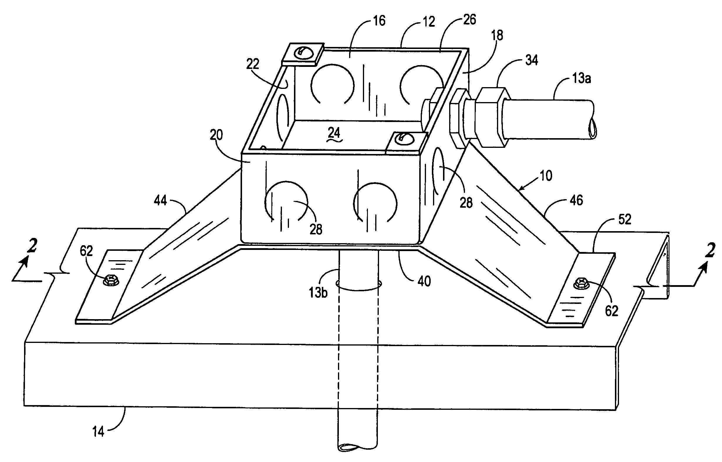
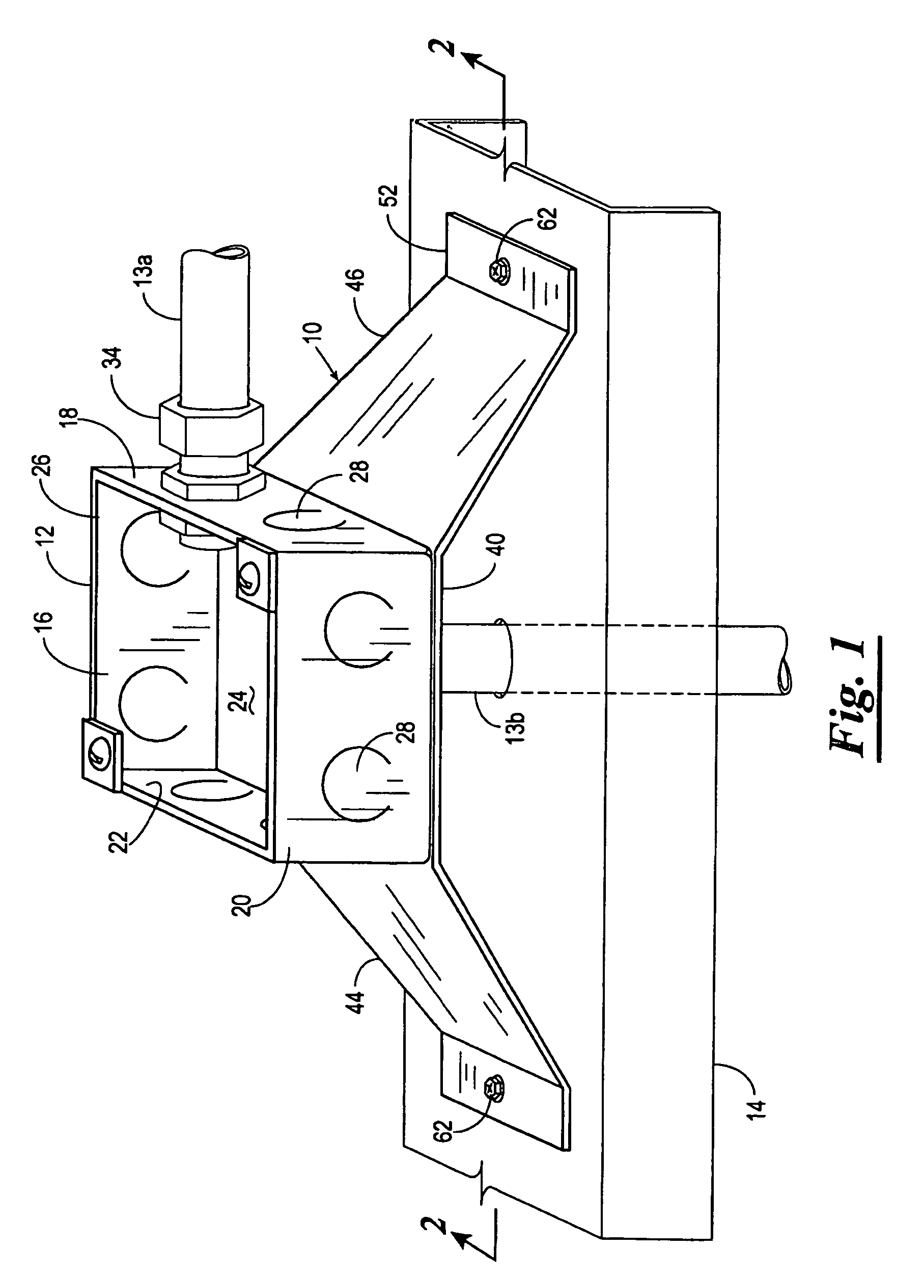
[0010]Referring now to the drawings, and more particularly to FIG. 1, a support bracket 10, constructed in accordance with the present invention, for supporting an electrical junction box 12 and a plurality of conduits 13a and 13b on a support member 14 is shown. The electrical junction box 12 is generally rectangular in shape, having four side walls 16, 18, 20, and 22, a rear wall 24, and an open front 26. The side and rear walls 16–24 have a plurality of knockouts 28. The knockouts 28 are easily removed to provide conduit receiving openings and thereby allow a conduit, such as conduits 13a and 13b to be attached to the junction box 12 at that location for wiring of the junction box 12.

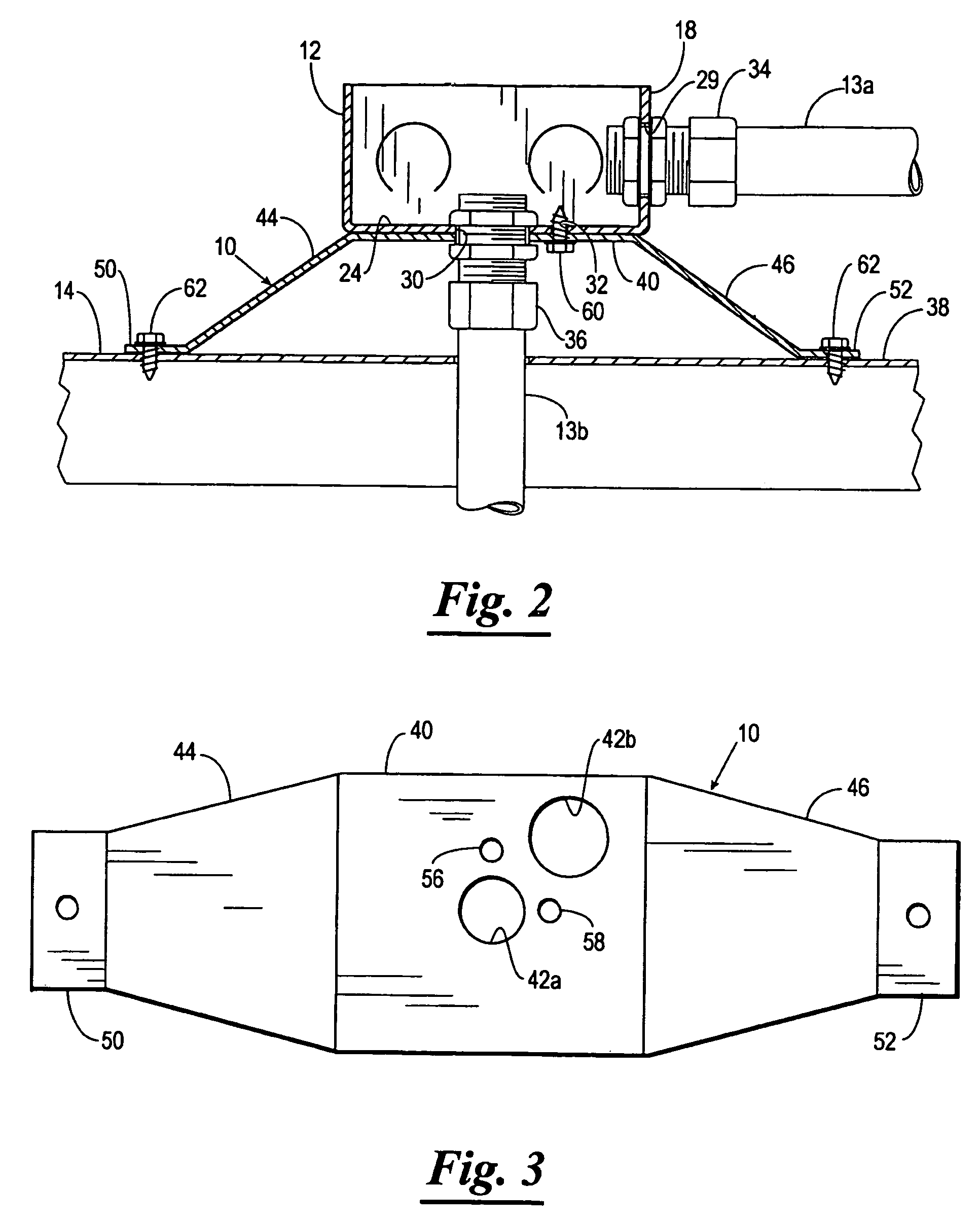
[0011]The conduit 13a is shown extending from a conduit receiving opening 29 (FIG. 2) of the side wall 18, and the conduit 13b is shown extending from a conduit receiving opening 30 of the rear wall 24 out and through a hole formed in the support member 14. Two mounting holes 31 and 32 are provided t...


PUM


Abstract

A support bracket and method for supporting an electrical junction box. The support bracket has a substantially flat base with a pair of conduit receiving holes, a pair of legs extending from the base at an angular relationship to the base, and a flange extending from each of the legs at an angular relationship such that each flange is substantially parallel to the base. The junction box is connected to the base of the support bracket with a junction box and the base in a face to face contact and a conduit receiving opening of the junction box aligned with one of the conduit receiving holes of the support bracket.

Description

CROSS REFERENCE TO RELATED APPLICATIONS[0001]Not applicable.BACKGROUND OF THE INVENTION[0002]1. Field of the Invention[0003]The present invention relates generally to mounting brackets, and more particularly, but not by way of limitation, to a bracket for supporting an electrical junction box.[0004]2. Brief Description of the Related Art[0005]Safety regulations require that wires carrying electrical current for operating lighting devices, motors, and other apparatus in buildings be strung safely and securely from each connection point to the next. The regulations require that connection points be within protective enclosures, such as outlet boxes, junction boxes, cabinets, and the like. Also, at least with respect to junction boxes, regulations require that the junction boxes be secured in position. In commercial buildings, the wires that extend from one junction box to the next are routed within a rigid, hollow conduit for protection. However, junction boxes that are located above ...

Claims


Application Information

Patent Timeline
IPC IPC(8): H02G3/08
CPCH02G3/126Y10S248/906
Inventor TOMPKINS, PHILIP M.
Owner TOMPKINS PHILIP M
Why Eureka
Try Eureka