Electrical junction box

a junction box and electric technology, applied in the direction of electrical apparatus casings/cabinets/drawers, gaseous cathodes, coupling device connections, etc., can solve the problems of damage to the electrical wire w, and increased cost of dies for forming the upper cover. to achieve the effect of reliable positioning of the terminal cover on the casing body

Inactive Publication Date: 2008-06-26
SUMITOMO WIRING SYST LTD
View PDF7 Cites 42 Cited by
  • Summary
  • Abstract
  • Description
  • Claims
  • Application Information

AI Technical Summary

Benefits of technology

[0033]In addition, as described above, the positioning rib is provided on the outer surface of the second divided member having no bulged portion for fitting the electrical wire. The positioning recess is provided in the outer surface of the

Problems solved by technology

However, when peripheral parts are arranged near a bottom wall of the electrical junction box, when the electrical wire w is drawn downward, the electrical wire w can be damaged due to interference between the electrical wire and the peripheral parts.
When such cover wall is provided on the upper cove

Method used


Image

  • Electrical junction box
  • Electrical junction box
  • Electrical junction box

Examples


Embodiment Construction

[0044]Referring now to the drawings, an exemplary embodiment of an electrical junction box is described below.

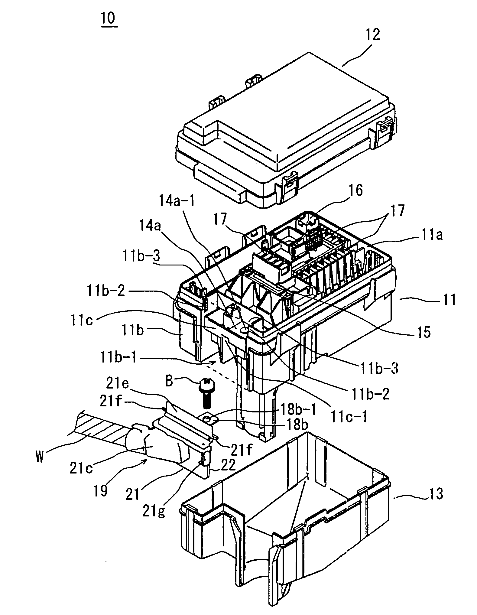
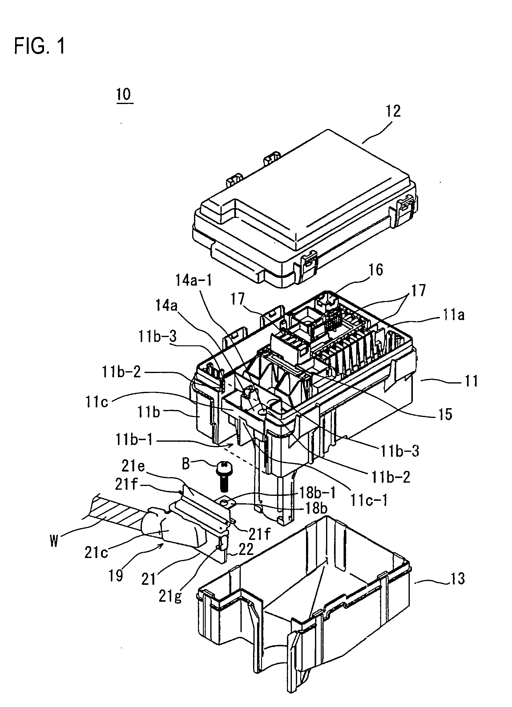
[0045]FIGS. 1 to 6 show an embodiment of an electrical junction box 10. The electrical junction box 10 includes a casing body 11, an upper cover 12 mounted on an upper surface of the casing body 11, and a lower cover 13 mounted on a lower surface of the casing body 11.

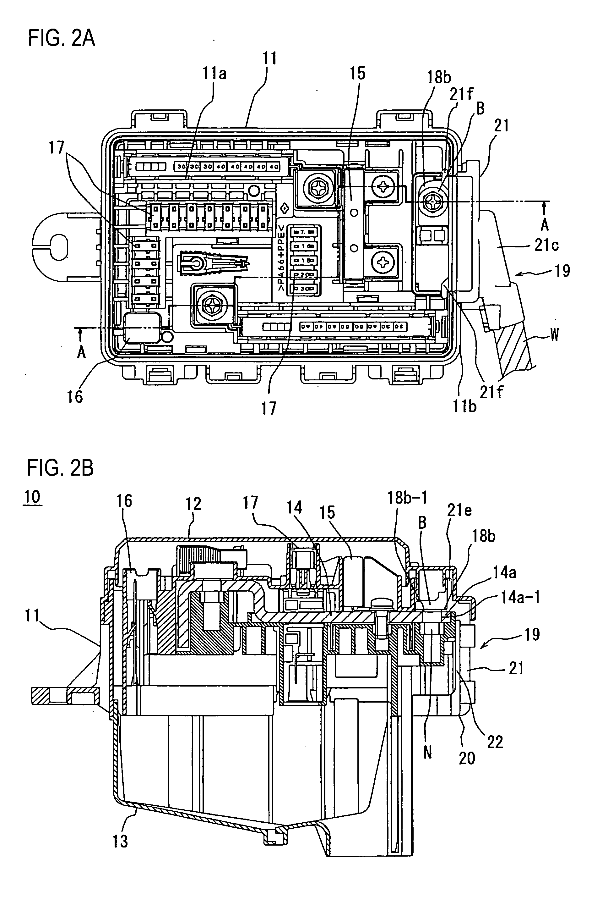
[0046]As shown in FIGS. 1 to 2B, the casing body 11 contains a bus bar 14 that serves as an internal circuit. The casing body 11 is provided on an upper surface 11a with a fusible link mounting section 15, a relay containing section 16, and a fuse containing section 17. The casing body 11 is provided along an outer edge of the upper surface 11a with a terminal portion 14a of the bus bar 14 connected to a bolt-fastened terminal 18 on an end of an electrical wire w.

[0047]As shown in FIG. 3, the bolt-fastened terminal 18 comprises an electrical wire pressing section 18a and an electrical contact section 18b. The e...


PUM


Abstract

An electrical junction box includes a casing body containing a bus bar that serves as an internal circuit. A bus bar terminal portion is disposed on an outer edge of an upper surface of the casing body to be connected to a terminal. An electrical wire, on which the terminal is calked, is arranged horizontally along an outer side wall of the casing body. A terminal cover encloses an electrical wire pressing section of the terminal. The terminal cover is fitted in a depression provided in the outer side wall of the casing body.

Description

[0001]This application claims priority from Japanese Patent Application No. 2006-342147 filed in the Japanese Patent Office on Dec. 20, 2006, the disclosure of which is incorporated herein by reference in its entirety.BACKGROUND[0002]Exemplary embodiments of the invention relate to an electrical junction box and more particularly an electrical junction box to be mounted on a motor vehicle. A bus bar is contained in a casing body of the electrical junction box and an electrical wire connected to the bus bar is arranged along an outer side wall of the electrical junction box to prevent interference between the electrical wire and other parts disposed around the electrical junction box.[0003]Generally, in an electrical junction box to be mounted on a motor vehicle, a bus bar that serves as an internal circuit is contained in a casing body. The bus bar is connected to a relay, a fuse, and the like and is accommodated in a fuse containing section and a relay containing section of the cas...

Claims


Application Information

Patent Timeline
IPC IPC(8): H05K5/00
CPCH05K7/026Y10S439/949
Inventor ODA, AKIHIRO
Owner SUMITOMO WIRING SYST LTD
Why Eureka
Try Eureka