This helps you quickly interpret patents by identifying the three key elements:
Problems solved by technology
Method used
Benefits of technology
Problems solved by technology
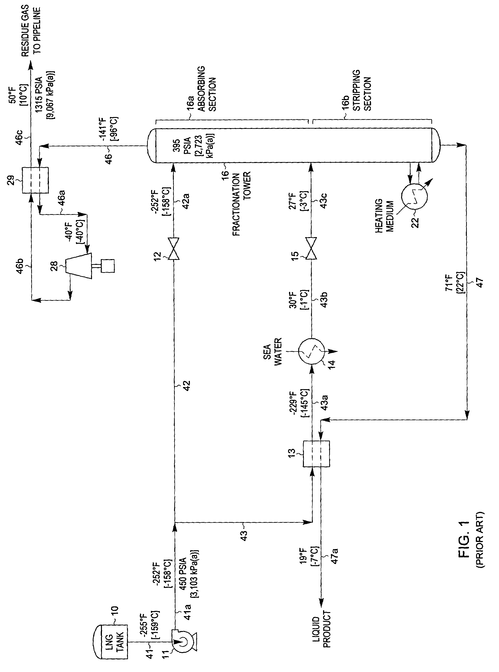
However, comparing the utilities consumptions in Table IV with those in Table I shows that the high level utility heat required for the FIG. 4 process is much higher than that for the FIG. 1 process because the FIG. 4 process does not allow for optimum use of low level utility heat.
Method used
Image
Click on the blue label to locate the original text in one second.
Reading with bidirectional positioning of images and text.
Examples
example 1
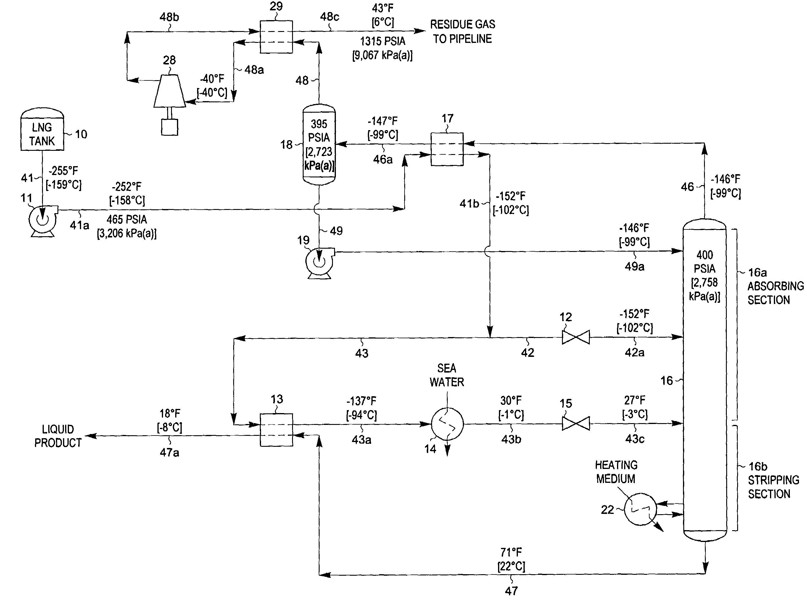
[0059]FIG. 10 illustrates a flow diagram of a process in accordance with the present invention. The LNG composition and conditions considered in the process presented in FIG. 10 are the same as those in FIGS. 1, 4, and 7. Accordingly, the FIG. 10 process can be compared with that of the FIGS. 1, 4, and 7 processes to illustrate the advantages of the present invention.
[0060]In the simulation of the FIG. 10 process, the LNG to be processed (stream 41) from LNG tank 10 enters pump 11 at −255° F. [−159° C.]. Pump 11 elevates the pressure of the LNG sufficiently so that it can flow through heat exchangers and thence to fractionation tower 16. Stream 41a exiting the pump is heated to −152° F. [−102° C.] in reflux condenser 17 as it provides cooling to the overhead vapor (stream 46) from fractionation tower 16. Stream 41b exiting reflux condenser 17 is split into two portions, streams 42 and 43. The first portion, stream 42, is expanded to the operating pressure (approximately 400 psia [2,...
example 2
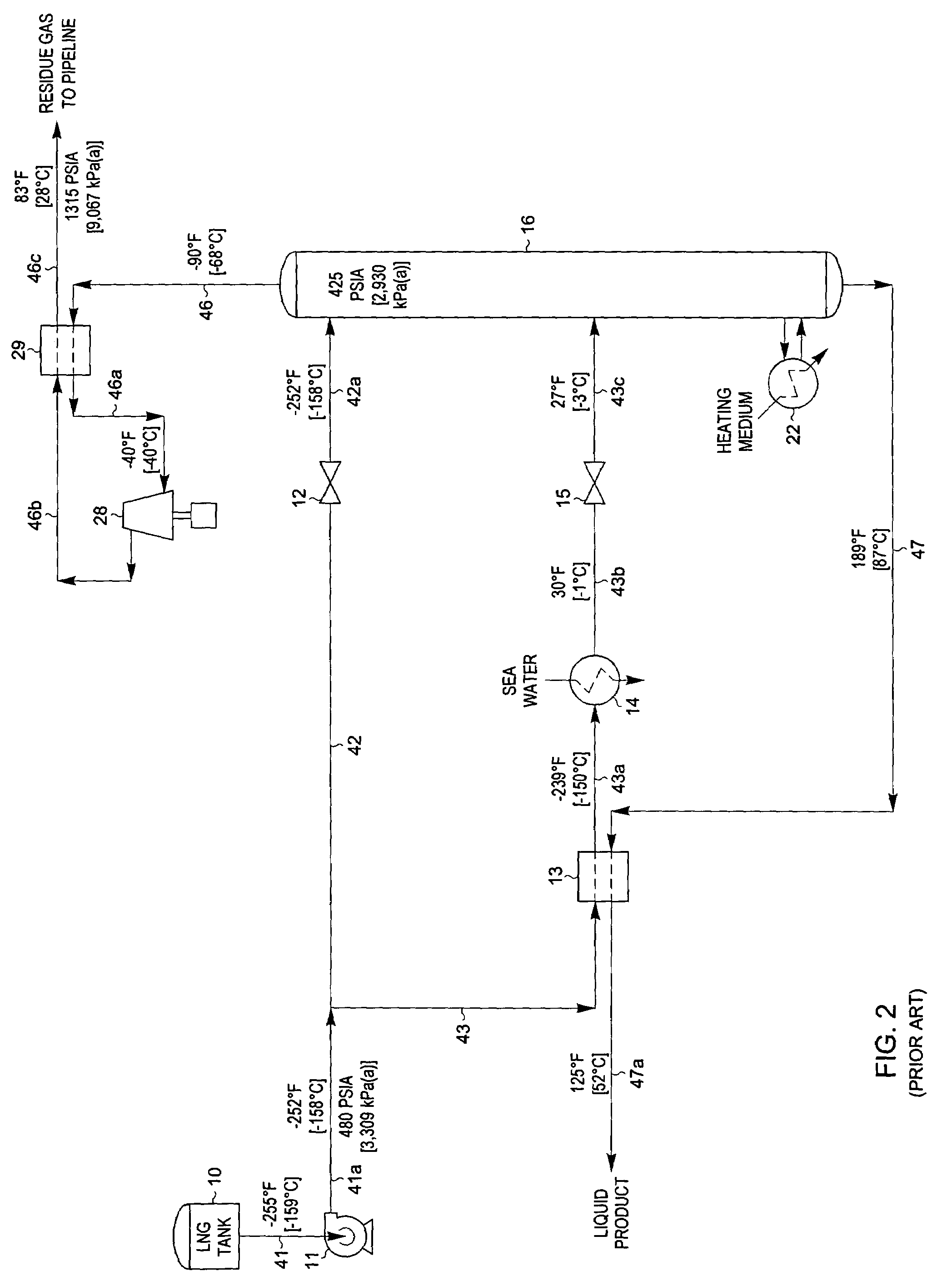
[0070]The present invention can also be adapted to produce an LPG product containing the majority of the C3 components and heavier hydrocarbon components present in the feed stream as shown in FIG. 11. The LNG composition and conditions considered in the process presented in FIG. 11 are the same as described previously for FIGS. 2, 5, and 8. Accordingly, the FIG. 11 process of the present invention can be compared to the prior art processes displayed in FIGS. 2, 5, and 8.
[0071]The processing scheme for the FIG. 11 process is essentially the same as that used for the FIG. 10 process described previously. The only significant differences are that the heat input of reboiler 22 has been increased to strip the C2 components from the liquid product (stream 47) and the operating pressure of fractionation tower 16 has been raised slightly.
[0072]The liquid product stream 47 exits the bottom of deethanizer 16 at 189° F. [87° C.], based on an ethane to propane ratio of 0.020:1 on a molar basis...
example 3
[0077]If a slightly lower recovery level is acceptable, another embodiment of the present invention may be employed to produce an LPG product using much less power and high level utility heat. FIG. 12 illustrates such an alternative embodiment. The LNG composition and conditions considered in the process presented in FIG. 12 are the same as those in FIG. 11, as well as those described previously for FIGS. 3, 6, and 9. Accordingly, the FIG. 12 process of the present invention can be compared to the embodiment displayed in FIG. 11 and to the prior art processes displayed in FIGS. 3, 6, and 9.
[0078]In the simulation of the FIG. 12 process, the LNG to be processed (stream 41) from LNG tank 10 enters pump 11 at −255° F. [−159° C.]. Pump 11 elevates the pressure of the LNG sufficiently so that it can flow through heat exchangers and thence to absorber column 16. Stream 41a exiting the pump is heated first to −91° F. [−69° C.] in reflux condenser 17 as it provides cooling to the overhead v...
PUM
Abstract
A process and apparatus for the recovery of ethane, ethylene, propane, propylene, and heavier hydrocarbons from a liquefied natural gas (LNG) stream is disclosed. The LNG feed stream is directed in heat exchanger relation with a warmer distillation stream rising from the fractionation stages of a distillation column, whereby the LNG feed stream is partially heated and the distillation stream is partially condensed. The partially condensed distillation stream is separated to provide volatile residue gas and a reflux stream, whereupon the reflux stream is supplied to the column at a top column feed position. A portion of the partially heated LNG feed stream is supplied to the column at an upper mid-column feed point, and the remaining portion is heated further to partially or totally vaporize it and thereafter supplied to the column at a lower mid-column feed position. The quantities and temperatures of the feeds to the column are effective to maintain the column overhead temperature at a temperature whereby the major portion of the desired components is recovered in the bottom liquid product from the column.
Description
BACKGROUND OF THE INVENTION[0001]This invention relates to a process for the separation of ethane and heavier hydrocarbons or propane and heavier hydrocarbons from liquefied natural gas, hereinafter referred to as LNG, to provide a volatile methane-rich residue gas stream and a less volatile natural gas liquids (NGL) or liquefied petroleum gas (LPG) stream.[0002]As an alternative to transportation in pipelines, natural gas at remote locations is sometimes liquefied and transported in special LNG tankers to appropriate LNG receiving and storage terminals. The LNG can then be re-vaporized and used as a gaseous fuel in the same fashion as natural gas. Although LNG usually has a major proportion of methane, i.e., methane comprises at least 50 mole percent of the LNG, it also contains relatively lesser amounts of heavier hydrocarbons such as ethane, propane, butanes, and the like, as well as nitrogen. It is often necessary to separate some or all of the heavier hydrocarbons from the meth...
Claims
Application Information
Patent Timeline
Application Date:The date an application was filed.
Publication Date:The date a patent or application was officially published.
First Publication Date:The earliest publication date of a patent with the same application number.
Issue Date:Publication date of the patent grant document.
PCT Entry Date:The Entry date of PCT National Phase.
Estimated Expiry Date:The statutory expiry date of a patent right according to the Patent Law, and it is the longest term of protection that the patent right can achieve without the termination of the patent right due to other reasons(Term extension factor has been taken into account ).
Invalid Date:Actual expiry date is based on effective date or publication date of legal transaction data of invalid patent.

