Method and apparatus for flow control

Active Publication Date: 2007-01-02
LANCER PARTNERSHIP
View PDF51 Cites 72 Cited by
  • Summary
  • Abstract
  • Description
  • Claims
  • Application Information

AI Technical Summary

Benefits of technology

[0018]One technical advantage, among others, of the present inve

Problems solved by technology

However, due to variations in the systems, such as, without limitation, pressure changes,

Method used


Image

  • Method and apparatus for flow control
  • Method and apparatus for flow control
  • Method and apparatus for flow control

Examples


Embodiment Construction

[0025]The present application is a continuation-in-part of U.S. patent application Ser. No. 10 / 351,673, filed Jan. 28, 2003, entitled “ELECTROMAGNETICALLY ACTUATED PROPORTIONAL FLOW SYSTEM,” which is herein incorporated by reference in its entirety.

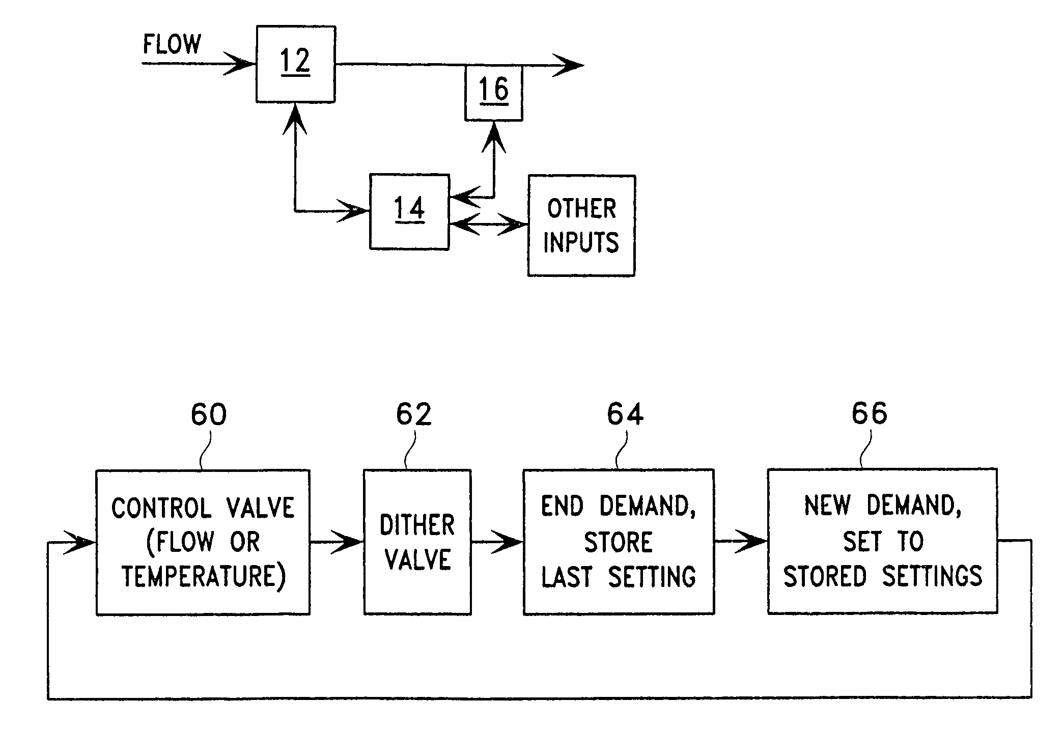
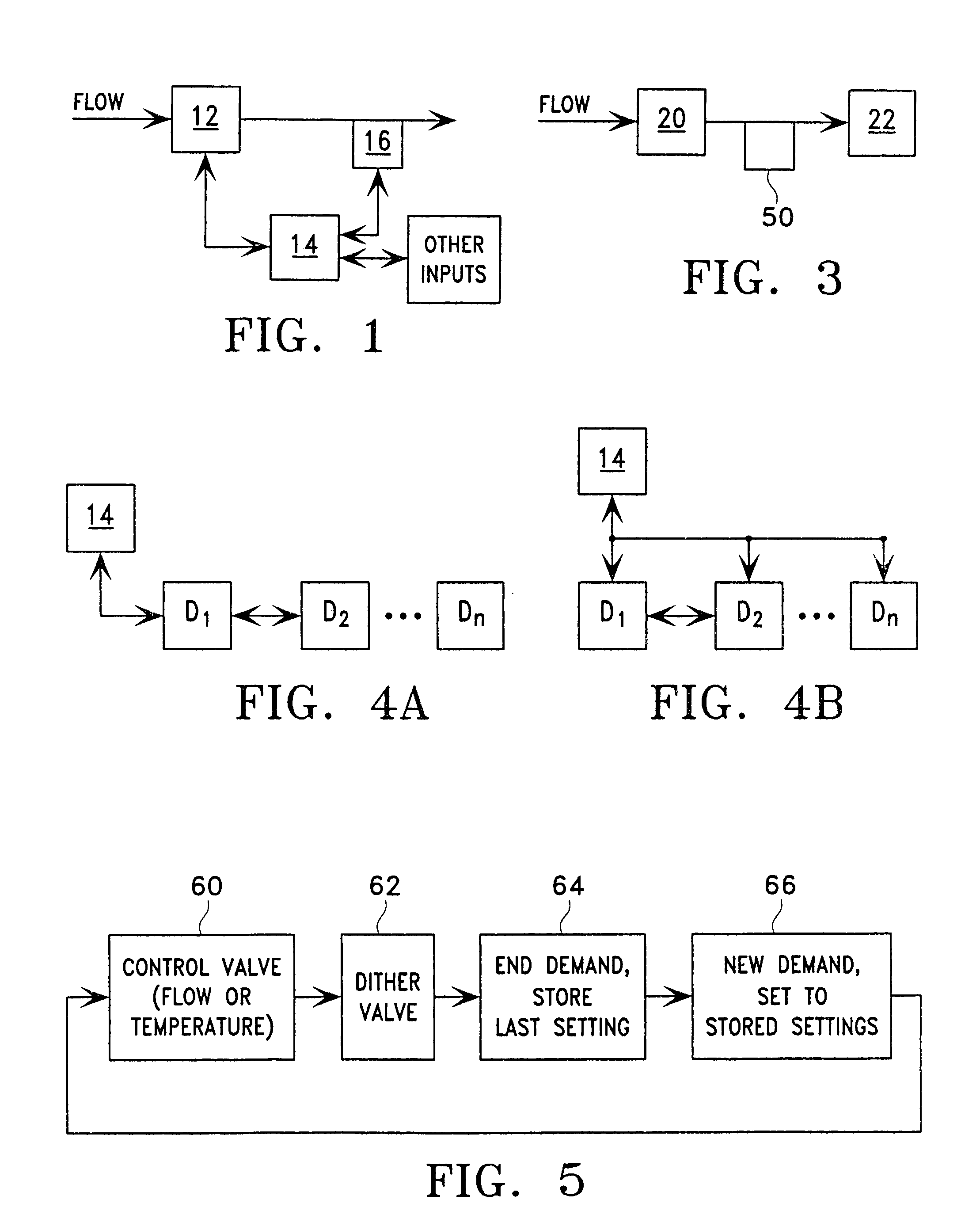
[0026]FIG. 1 is a block diagram of one embodiment of a flow control system 10 according to the teachings of the present invention. As shown in FIG. 1, a flow control valve 12 is coupled to a control system 14. Control system 14 is also coupled to a sensor 16. In the particular embodiment shown in FIG. 1, sensor 16 is shown downstream of the valve 12. However, it should be understood that the sensor 16 may be upstream or downstream, and may comprise one or more sensors upstream, downstream or both.

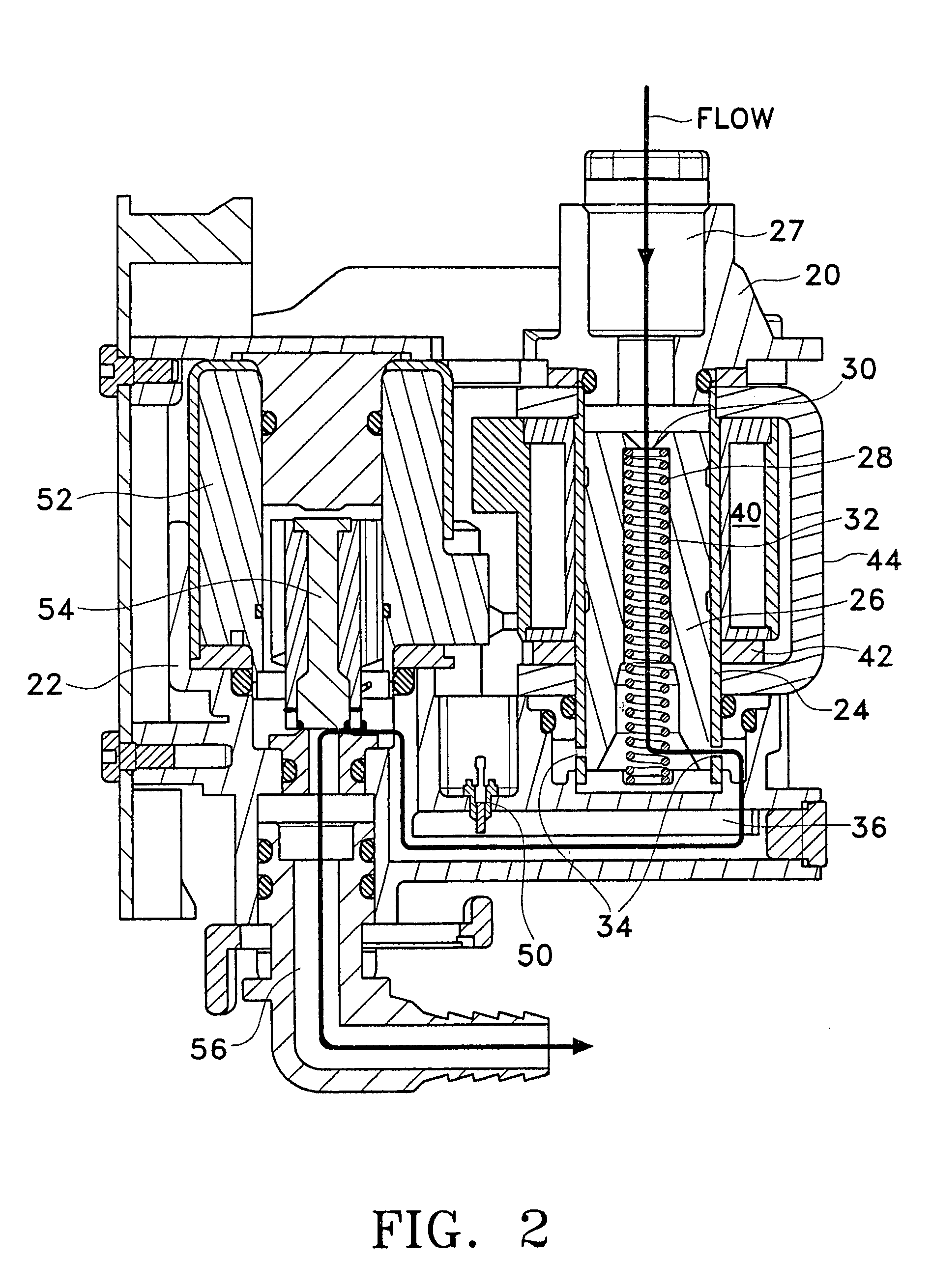
[0027]FIG. 2 illustrates a sectional view of a particular embodiment of the valve 12. The valve 12 includes a flow control solenoid valve 20 and a shut-off valve 22. In the particular configuration shown in FIG. 2, fluid flows first through the v...


PUM


Abstract

A flow control system (10) is provided in which a flow control valve (12) is controlled by a control system (14). The control system (14) measures a flow rate or temperature of a fluid flowing through the flow control valve (12) and adjusts the flow control valve (12) to achieve a desired flow rate. The flow control valve (12) includes an electromagnetically adjustable spool (26).

Description

RELATED APPLICATION INFORMATION[0001]This application is a continuation-in-part of U.S. patent application Ser. No. 10 / 351,673, filed Jan. 28, 2003 now abandoned, entitled Electromagnetically Actuated Proportional Flow System.TECHNICAL FIELD OF THE INVENTION[0002]This invention relates generally to flow control.BACKGROUND OF THE INVENTION[0003]Control of the flow of one or more liquids is desirable in many applications. For example, without limitation, where liquids are to be mixed in particular proportions, or where particular amounts of liquids are desired, it is often desirable to control the flow rates to ensure the proper mixture or amount. Typically, as part of this control, a sensor is used to measure flow rate, and a control device, such as a valve, is adjusted in response to the sensed flow rate to achieve the desired flow rate.[0004]A particular application where flow control is desirable is in the dispensing of post-mix beverages. In post-mix beverage systems, beverage sy...

Claims


Application Information

Patent Timeline
IPC IPC(8): G05D11/13B67D5/56B67D7/74G05D7/06
CPCG05D7/0635Y10T137/0329Y10T137/2514Y10T137/2529Y10T137/2703
Inventor EVERETT, WILLIAM F.SUDOLCAN, DAVID C.
Owner LANCER PARTNERSHIP
Why Eureka
Try Eureka