Liquid leakage sensor and liquid leakage detecting system

a leakage sensor and liquid leakage detection technology, which is applied in the field of liquid leakage sensors and liquid leakage detection systems, can solve the problems of leaking liquid over the upper surface of the holder, the reliability of the liquid leakage detection system is very improved, and the leakage liquid cannot be resolved. the effect of accurate installation of each sensor

Active Publication Date: 2007-01-02
TOYOKOKAGAKU +1
View PDF7 Cites 9 Cited by
  • Summary
  • Abstract
  • Description
  • Claims
  • Application Information

AI Technical Summary

Benefits of technology

[0015]Further, another object of the invention is to provide a liquid leakage sensor and a liquid leakage detecting system wherein plural liquid leakage sensors are installed into a control system at each specified group unit with wired-OR connected external outputs, and in case of issuing a warning signal from the system after detecting any error, it is enabled for the maintenance operator of the plant system to accurately and easily identify the spatial position / location of the really error-activated sensor among plural sensors in the commonly-connected group unit.
[0031]And, in the liquid leakage sensor and the liquid leakage detecting system of the present invention, a small amount of a leaking liquid can be accurately detected for an electrically conductive liquid such as a water, an acid solution, or an alkaline solution, etc., and a liquid having an insulating property such as a super pure water, an organic solution of an alcohol, a thinner, or a benzine, etc. Further, a very small amount of a leaking liquid can be detected at high speed for a liquid having a low surface tension of 6×10⁻² N / m or less at 20° C., particularly, even for a liquid having a low surface tension of 3×10⁻² N / m or less at 20° C. and having a diffusing characteristics such as a very thin layer.

Problems solved by technology

However, since the number of joints connecting these pipes is very numerous, there are many cases in which a liquid is leaked from these joints.
So that it takes a long time for the leaking liquid to diffuse over the upper surface of the holder.
Consequently, the following problems cannot be resolved, that is, a small amount of a leaking liquid cannot be detected at all, or too many times are wasted until a detection of a bit of a liquid is started.
After issuing the warning signal related to the plural leakage sensors, a maintenance problem of a system in a plant occurs, that is, an operator cannot identify quickly where is the error-activated sensor in order to spatially access and repair the abnormal condition among commonly connected plural sensors.
Furthermore, from a view point of the environmental working-conditions, liquid leakage sensors are generally installed at the lowermost portion of a system such as a floor surface, or a liquid storing pan, etc. and various system components are placed at an upper space of the system, therefore, another maintenance problem also occurs in which a light emitting-type alarm display-means such as LED, etc. attached to the liquid leakage sensor itself is functioning very difficult to visually recognize the location of an error-activated sensor among plural sensors, and it is generally difficult to identify easily the location of a leak-activated sensor through the display means installed at the lowermost portion of the system.
However, in a practical sense, it is impossible to require such a registering operation for one operator wherein he must accurately install more than forty sensors at each specified location, then execute wiring operation without any mistakes, at next step register and verify each installation location of respective sensor accurately.
In a system installation, if plural workers are admitted in the installation work of the leakage sensors, a purchase price of the sensors is unnecessarily sky-rocketed.
Therefore, for an operator of the sensor installation, the technique disclosed in the patent literature 2 is completely useless in a practical sense.
Therefore, when any system failure is occurred in the parent, another problem is also invited wherein no warning signals can be issued from the parent while detecting any error conditions in a normal child sensor.
Therefore, another problem is also invited in the alarming system of the patent literature 2 wherein as for a new-coming operator or an operator insufficient in a memory power / a learning ability, the announcing system consisting of warning voice messages is completely useless in order to repair or exchange the error-activated leakage sensor.
Because a liquid leakage sensor is generally installed at a narrow lower space near a floor surface and can be easily interfered with a passing space of an operator.

Method used


Image

  • Liquid leakage sensor and liquid leakage detecting system
  • Liquid leakage sensor and liquid leakage detecting system
  • Liquid leakage sensor and liquid leakage detecting system

Examples


Embodiment Construction

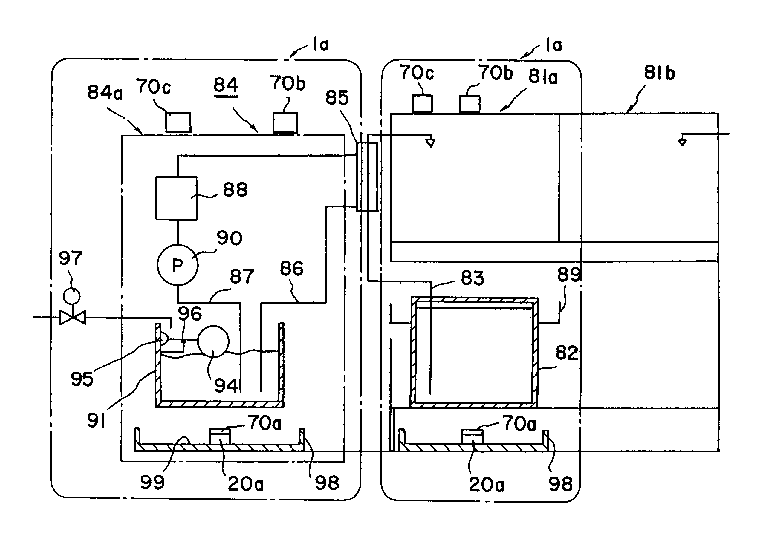
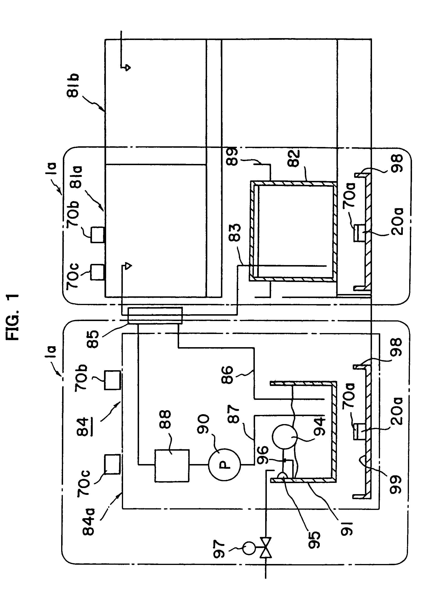
[0041]A liquid leakage detecting system of the present invention is including at least one liquid leakage sensor having at least one detecting portion contactable with a leaking liquid through an air layer or a liquid permeable layer and comprising:[0042]plural sensors detecting a leaking liquid and connected commonly each other with external outputs;[0043]warning means including a sound producing means; and[0044]said warning means is installed within a specified spatial distance from each installation position of said liquid leakage sensor, wherein after detecting error-activated liquid leakage sensor based on any abnormal conditions, a warning signal is issued at least in an audio frequency based on said warning means in order to distinguish said activated leakage sensor from other non-activated leakage sensors installed outside of said specified spatial distance and uniquely identify the installation position of said activated leakage sensor.

[0045]It is preferable for a single or...


PUM


Abstract

Among plural liquid leakage sensors placed at the lower most portion of a system such as a floor surface, a leaked liquid storing portion, etc., an error-activated location of the sensor can be easily identified uniquely when the sensor is detecting any abnormality. In a liquid leakage detecting system including at least one liquid leakage sensor having at least one detecting portion contactable with a leaking liquid through an air layer or a liquid permeable layer, a warning device including a sound producing is placed within a specified spatial distance from each installation position of the liquid leakage sensor, wherein after detecting any abnormal conditions of the liquid leakage sensor, a warning signal is issued at least in an audio frequency based on the warning device in order to discriminate the error-activated leakage sensor from other non-activated leakage sensors placed outside of the specified spatial distance and uniquely identify the installation position of the activated leakage sensor.

Description

BACKGROUND OF THE INVENTION[0001]1. Field of the Invention[0002]The present invention relates to improvements of a liquid leakage sensor and a liquid leakage detecting system for detecting a leakage of an electrically conductive liquid such as a water, an acid solution, or an alkaline solution, etc., and a leakage of a liquid having an insulating property such as a super pure water, an organic solution of an alcohol, a thinner, or a benzine, etc.[0003]2. Background Art[0004]Conventionally, a liquid is supplied through piping in a facility of a factory, etc. However, since the number of joints connecting these pipes is very numerous, there are many cases in which a liquid is leaked from these joints. Therefore, an operator had to monitor a leaking liquid at all times according to the kinds of liquids. As such a conventional liquid leakage sensor, a leakage sensor based on measuring an electrical conductance between electrodes is known for determining a leakage from an impedance chang...

Claims


Application Information

Patent Timeline
Patent Type & Authority Patents(United States)
IPC IPC(8): G08B21/00G01M3/16
CPCG01M3/16
Inventor HAYASHIDA, TATEKAZUSHIMAI, FUTOSHIOMATA, YOHEY
Owner TOYOKOKAGAKU
Why Eureka
Try Eureka