Optical fiber coupler and manufacturing apparatus and method thereof

a manufacturing apparatus and optical fiber technology, applied in glass making apparatus, manufacturing tools, instruments, etc., can solve the problems of equipment not being made as compact as desired, more expensive, etc., and achieve the effect of improving the driving mechanism and operation of the manufacturing apparatus, reducing building costs, and improving the size of the apparatus

Inactive Publication Date: 2007-01-02
CORETECH OPTICAL
View PDF21 Cites 8 Cited by
  • Summary
  • Abstract
  • Description
  • Claims
  • Application Information

AI Technical Summary

Benefits of technology

[0009]In another aspect, the invention provides a packaging device for manufacturing optical fiber couplers that mainly includes a pedestal, a screw bar and a pair of carriers. The screw bar has two sections that have opposite screw threads formed respectively on the peripheral surface, and run horizontally through the base. The two carriers have screw holes with opposite screw threads to couple with the screw bar, and jointly hold a packaging substrate the top to package an optical fiber coupler. When the screw bar rotates, the two carriers are moved to reduce or increase the interval there between.
[0013]In short, the invention mainly aims to provide a loading fixture, a clamping device and a packaging station in the manufacturing process for fabricating 1×4, 2×4 or 4×4 optical fiber couplers. It also improves the driving mechanism and operation of the manufacturing apparatus of the optical fiber couplers. The size of the apparatus is greatly reduced, and the building costs are lower. The reliability and production yield of the manufacturing system of the optical fiber coupler also is enhanced.

Problems solved by technology

This is more expensive and the equipment cannot be made as compact as desired.

Method used


Image

  • Optical fiber coupler and manufacturing apparatus and method thereof
  • Optical fiber coupler and manufacturing apparatus and method thereof
  • Optical fiber coupler and manufacturing apparatus and method thereof

Examples


first embodiment

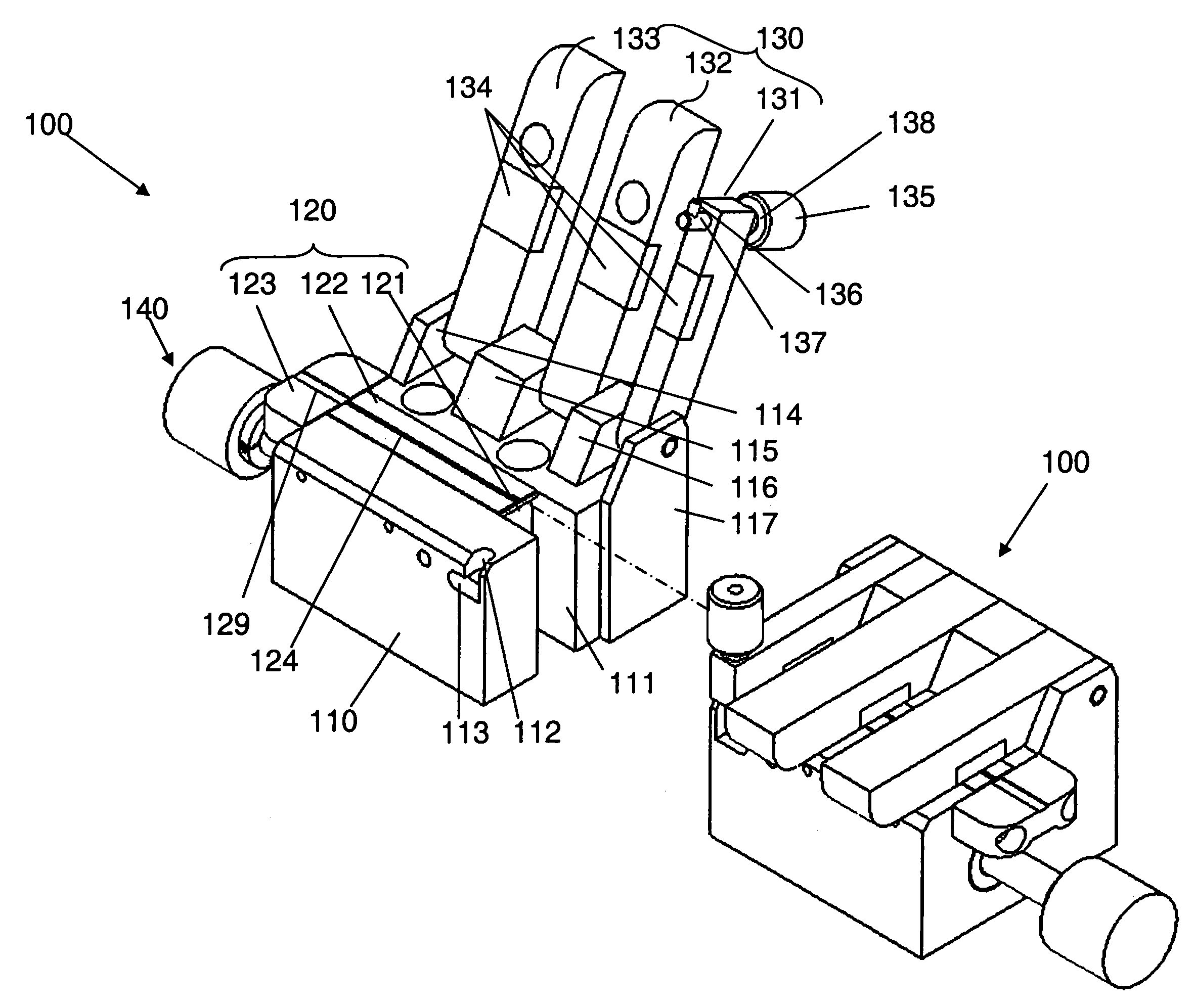
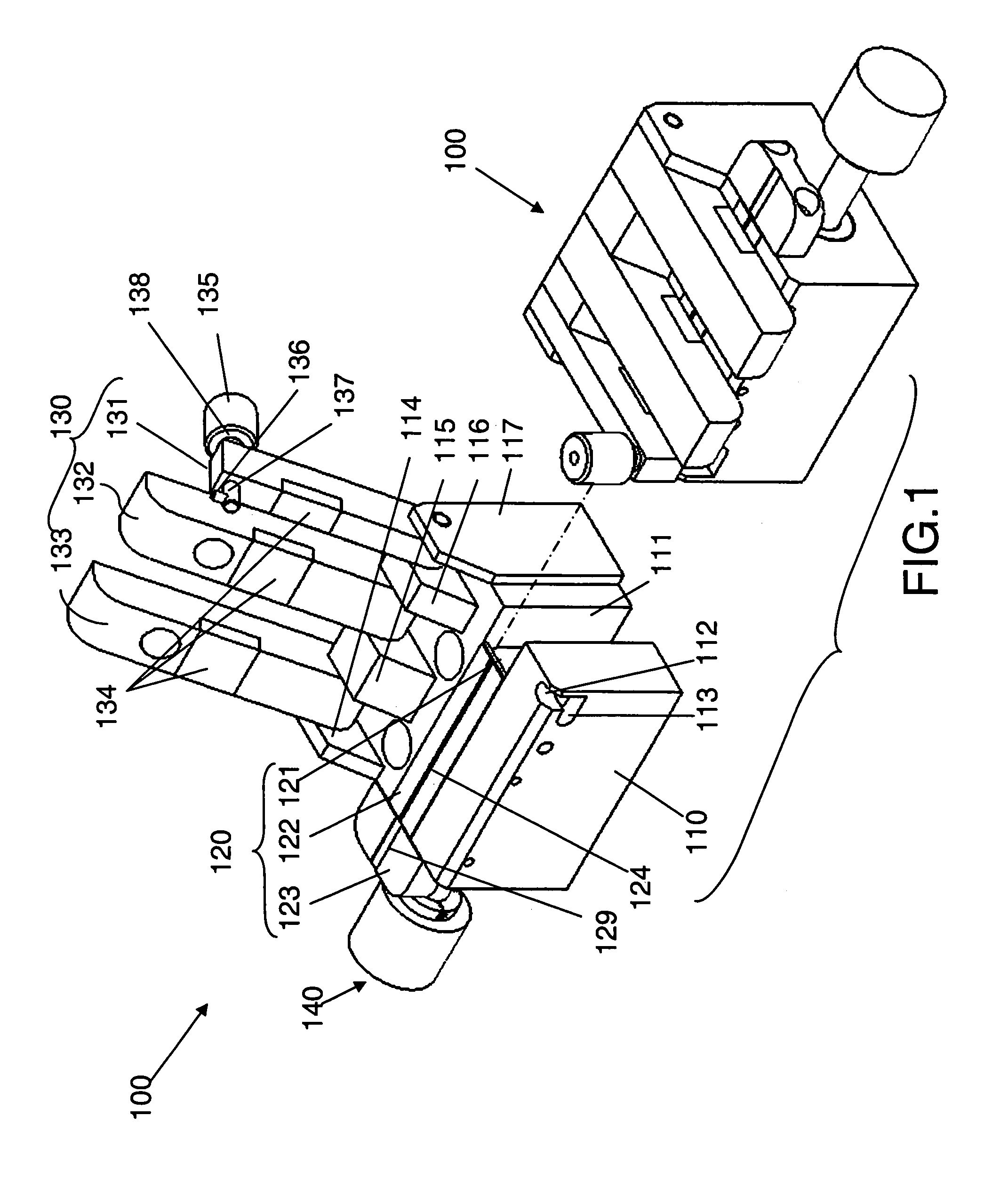
[0023]Refer to FIGS. 1 through 5 for the clamping device for fabricating the optical fiber coupler according to the invention. In general, two symmetrical clamping devices are to be used in a cooperative manner. The following discussion is based on one clamping device 100.

[0024]Referring to FIG. 1, the clamping device 100 includes a holding stage 110, a loading fixture 120, a clamping member 130 and a push rod 140.

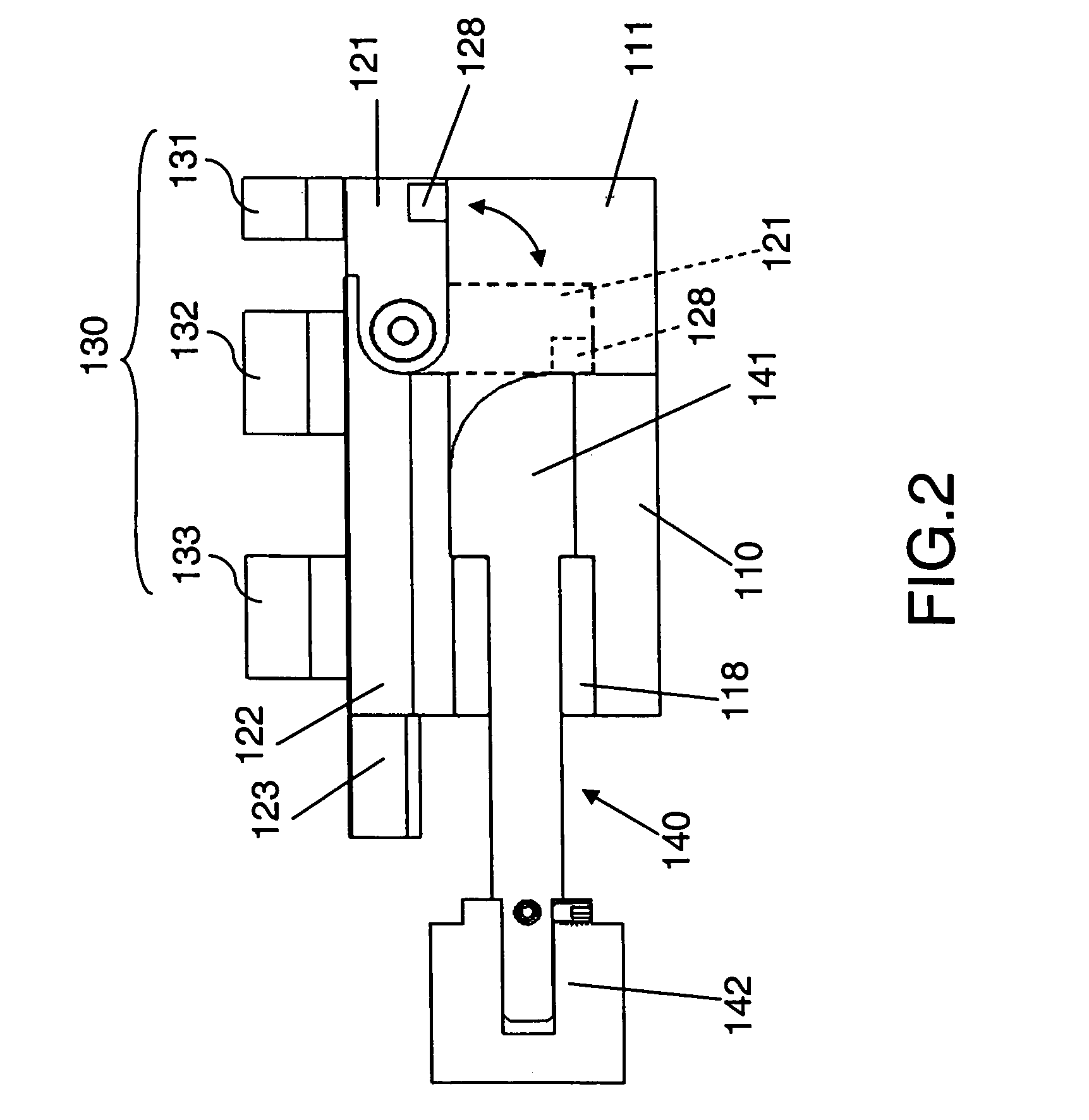
[0025]Referring to FIGS. 1 and 2, the holding stage 110 is made of metal and has a vertical trench 111. On a corner adjacent to the top surface of one side, there is a guiding slot 112 and an orienting slot 113 formed on one side. The top surface of the holding stage 110 further has pivot seats 114, 115, 116 and 117 to pivotally couple with the clamping member 130.

[0026]Referring to FIGS. 1 through 4, the loading fixture 120 is located on the top surface of the holding stage 110 opposing the trench 111. They may be integrally formed, or as shown in this embodiment, include...

second embodiment

[0027]The top surfaces of the anchoring section 122 and the packaging section 121 have a groove 124 to hold four optical fibers (referring to FIGS. 1, 3 and 4). The notch 129 of the plane deck 123 is abutting the groove 124 on the outer end of the anchoring section 122. The groove 124 has a first bottom surface 125, a second bottom surface 126 and a third bottom surface 127. The first bottom surface 125 is deeper than the second and third bottom surfaces 126 and 127, and they are formed in a stepwise manner. In FIG. 4, the sidewalls of the groove 124 are inclined. In practice, the sidewalls of the groove 124 may be in any shape desired, as long as they can hold the optical fibers. FIG. 5 shows a second embodiment in which the sidewalls are vertical. The bottom surfaces also may be formed in any shape desired, such as concave surfaces.

[0028]Referring to FIG. 4, for holding the optical fibers. Place a first optical fiber 151 on the first bottom surface 125, a second optical fiber 152 ...

third embodiment

[0036]Refer to FIGS. 6 and 7 for the packaging station 200 for fabricating optical fiber couplers. It includes a pedestal 210, a screw bar 220, carriers 230 and 240, and guiding rods 250 and 260.

[0037]The pedestal 210 is substantially formed in U-shape. The screw bar 220 runs through the pedestal 210 horizontally and has two ends extended outside the pedestal 210. The two distal ends of the screw bar 220 are coupled respectively with a rotary bar 221 and 222 of a larger diameter to be grasped for turning.

[0038]The carriers 230 and 240 are substantially vertical posts and have screw holes 231 and 241 of opposite screw threads to couple on the screw threads (not shown in the drawings) of the screw bar 220. The surface of the screw bar 220 has a left area and a right area with screw threads of opposite directions formed thereon. The guiding rods 250 and 260 run transversely through the pedestal 210 and anchor thereon in parallel with the screw bar 220. The carriers 230 and 240 have cor...


PUM

PropertyMeasurementUnit
included anglesaaaaaaaaaa

Abstract

An optical fiber coupler and manufacturing apparatus and method thereof aim to provide a loading fixture and a clamping device to fabricate 1×4, 2×4 and 4×4 optical fiber couplers, and also improve driving mechanisms and operation of the packaging station and the entire manufacturing equipment. The 1×4 optical fiber coupler fabricated by means of the invention can split an optical signal more evenly and has a higher production yield. The total size of the equipment is smaller and the structure is less complicated, and the construction cost is lower.

Description

FIELD OF THE INVENTION[0001]The present invention relates to an optical fiber coupler and manufacturing apparatus and method thereof, and particularly to an 1×4 optical fiber coupler structure and improvements on a loading fixture, a clamping device, a packaging device and a conveying mechanism for the manufacturing apparatus and method thereof.BACKGROUND OF THE INVENTION[0002]Optical communication technology has made great progress in recent years. In the past, optical fiber communication technology and optical fiber communication elements mainly were used on backbone networks. These days they are widely used in metropolitan optical communication networks. The vision of Fiber-To-The-Home (FTTH) is achievable in the near future.[0003]The optical fiber coupler, also called optical fiber splitter, is an essential element to implement FTTH. The optical fiber coupler usually is fabricated through a fused biconical tapered fiber coupling technique. The optical fiber passive device thus m...

Claims


Application Information

Patent Timeline
Patent Type & Authority Patents(United States)
IPC IPC(8): G02B6/36G02B6/00
CPCG02B6/2821G02B6/3636G02B6/3616G02B6/3664
Inventor CHOU, CHENG-TSALIOU, LI-MING
Owner CORETECH OPTICAL
Why Eureka
Try Eureka