Dental instrument

a technology for teeth and jaws, applied in the field of dental instruments, can solve the problems of reducing the overall success of composite restorations,

Active Publication Date: 2007-01-23
GARRISON DENTAL SOLUTIONS
View PDF5 Cites 12 Cited by
  • Summary
  • Abstract
  • Description
  • Claims
  • Application Information

AI Technical Summary

Benefits of technology

[0008]The present invention provides a dental instrument that can be used to both place a rubber-dam clamp and to place a ring for a sectional matrix system. The dental instrument is adapted to capture most ring systems, if not all ring systems, used in the field of dentistry, along with the ability to secure and place a rubber-dam clamp about a tooth to secure a rubber-dam in place. Furthermore, the dental instrument is configured to allow the tines of the instrument to avoid the patient's teeth when placing the ring and / or rubber-dam clamp and, further, to avoid entanglement with a previously positioned ring or the rubber-dam itself.
[0013]In other aspects, the first portions of the distal portions are offset from the plane. For example, the first portions of the distal portions may extend in a second plane, which is generally parallel to the first plane. In addition, the first portions may comprise arcuate portions. Furthermore, the first portions preferably include planar lower surfaces, which provide additional stability to the dental retaining ring when captured by the distal portions of the dental instrument.
[0020]In other aspects, the prongs have a length in a range of about 8 to 10 mm, more preferably in a range of about 7 to 9 mm to thereby minimize the contact of the prongs with the teeth or gums of the patient.

Problems solved by technology

Isolation is extremely important when performing a composite restoration because foreign materials, such as saliva, blood, tooth particles, amalgam and / or composite material, may get into the composite restoration and greatly hamper the success of the restoration.
Hence, the overall success of the composite restoration may be reduced.
However, when using a rubber-dam clamp forceps for placing a ring into the interproximal space of a restoration, the rubber-dam clamp forceps do not open far enough for certain ring systems.
In addition, when placing the ring, the lower end of the forceps can get entangled or interfere with the dam and / or a previously placed ring (as best appreciated from FIG. 30).
Further, the ring will often not stay in the proper position for placement between the teeth because it may have a tendency to rock or rotate up or down between the forceps' arms.
As a result, there is a risk that the ring will spring off the forceps.
This later situation could result in the patient swallowing a ring if the rubber-dam is not properly placed before starting the restoration.

Method used


Image

  • Dental instrument
  • Dental instrument
  • Dental instrument

Examples


first embodiment

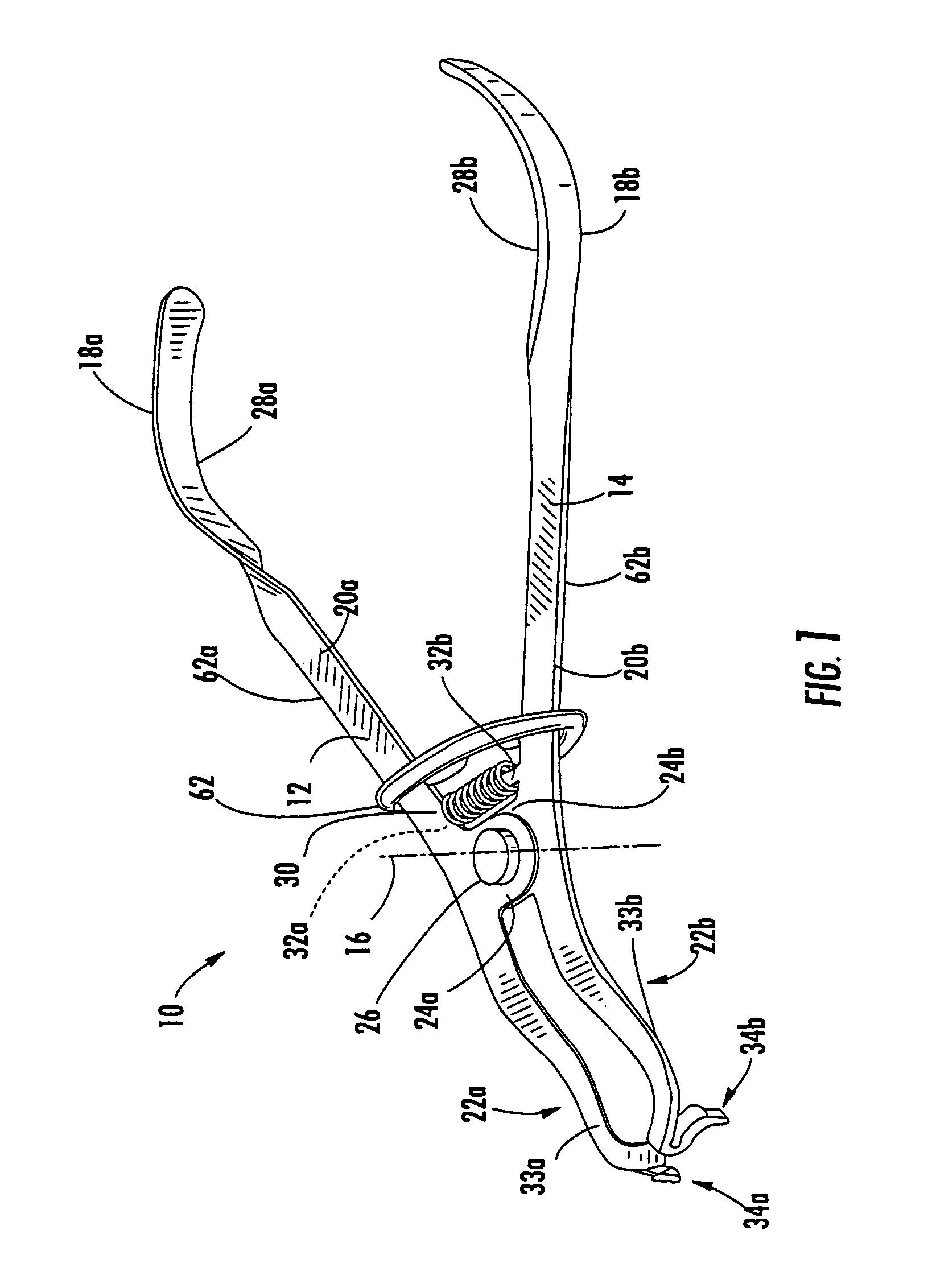
[0076]Referring to FIG. 14, the numeral 110 generally designates another embodiment of the dental instrument of the present invention. Dental instrument 110 is of similar construction to dental instrument 10 and includes a pair of arms 112 and 114, which are pivotally coupled about an axis 116 by a pin 126. Each arm 112 and 114 includes a proximal portion 118a, 118b, a medial portion 120a, 120b, and a distal portion 122a, 122b, respectively. For further details of proximal and medial portions 118a, 118b, 120a, 120b reference is made to the

second embodiment

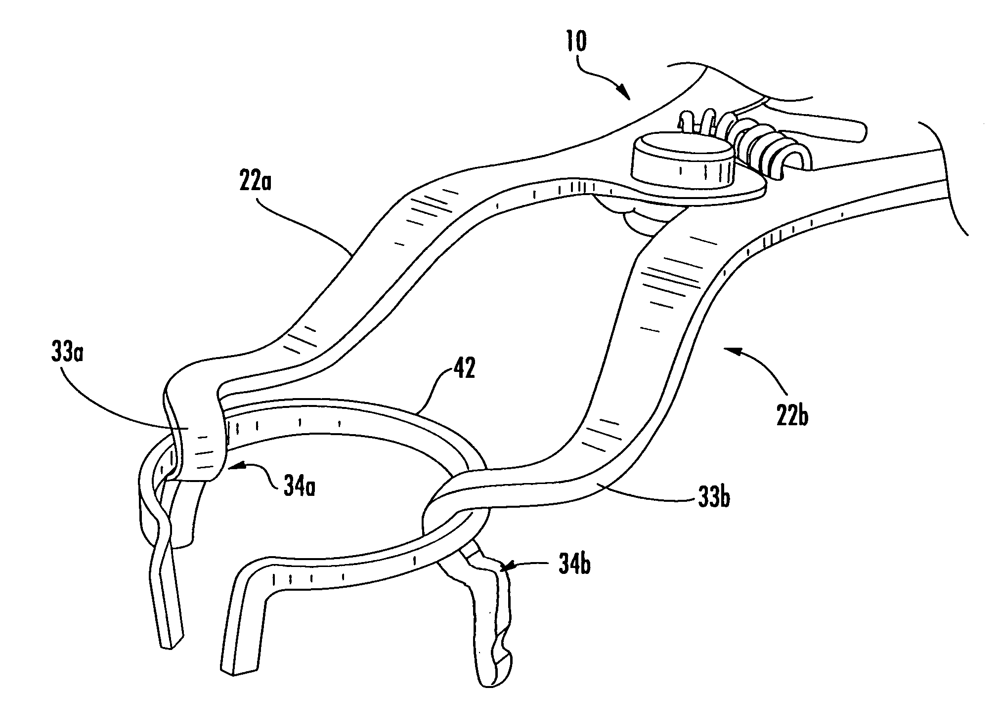
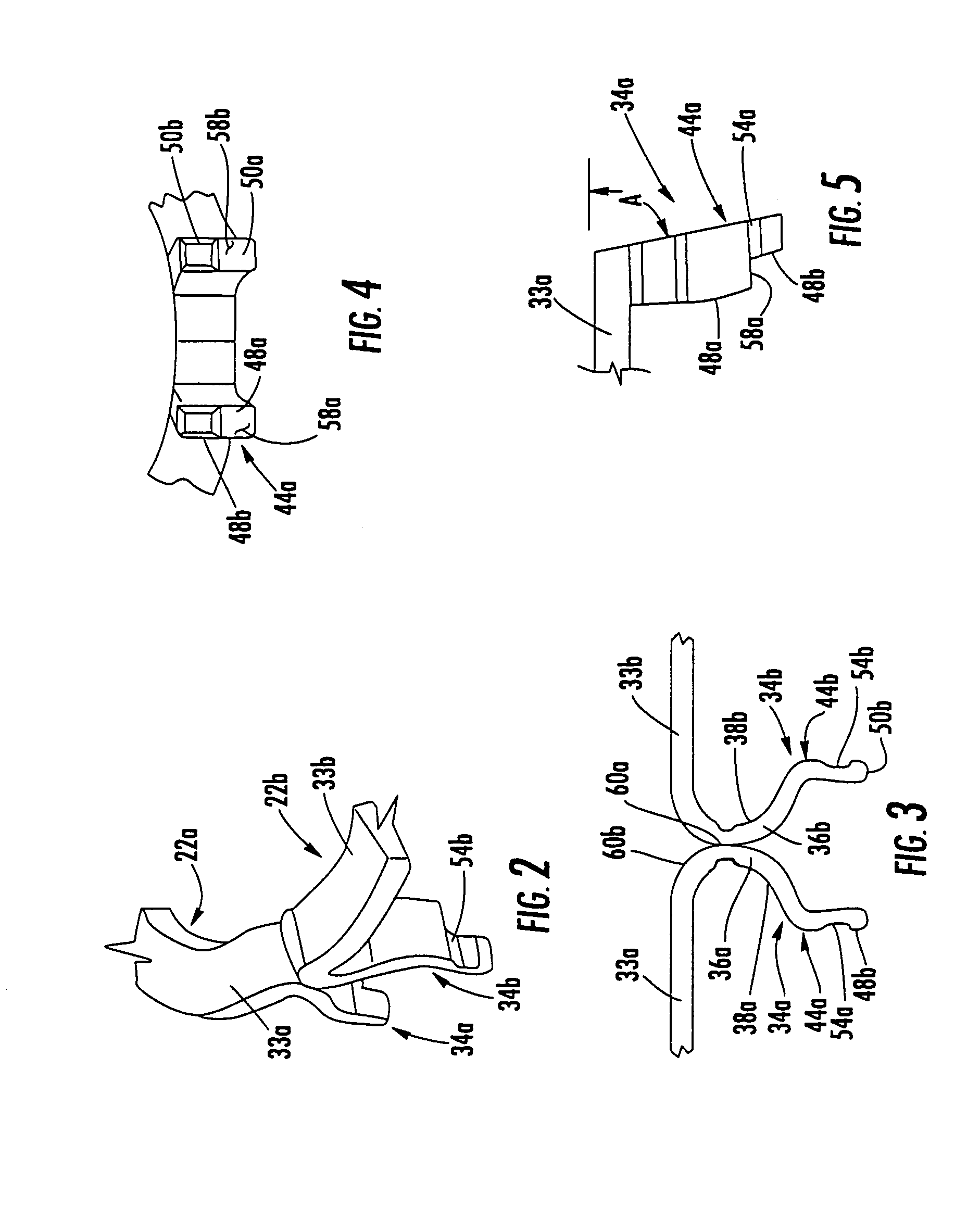
[0077]In the second embodiment, distal portions 122a and 122b include prongs 134a and 134b that depend from first portions 133a and 133b in a similar manner to the previous embodiment. However, in the present embodiment, prongs 134a and 134b include pivotal tines 144a and 144b, which are pivotally mounted to C-shaped portions 136a and 136b so that tines 144a and 144b may be rotated or pivoted between a stored position where they do not project below C-shaped portions to eliminate any potential interference with the placement of the ring 40 and an extended position (such as shown in FIG. 15) where lower or distal ends 148a and 150b are positioned for engaging a rubber-dam clamp. For example, tines 144a and 144b may be pivotally mounted to C-shaped portions 136a and 136b by pins 151a and 151b and, further, incorporate a detent mechanism so that the tines are held in their respective positions unless acted upon by a force sufficient to release the detent mechanism.

[0078]Referring to FI...


PUM


Abstract

A dental instrument includes a first arm, a second arm, which is pivotally coupled to the first arm about a pivot axis, and a spring. The first and second arms are pivotal with respect to each other in a plane generally orthogonal to the pivot axis. Each of the arms has a proximal portion, a medial portion, and a distal portion, with the proximal portions defining hand grip portions, and with the arms being pivotally connected at their medial portions. The spring biases the distal portions of the arms toward each other. Each of the distal portions comprises a first portion and a prong portion depending from the first portion. The prong portions comprise back-to-back generally C-shaped portions and spaced apart tines. The C-shaped portions define a pair of seats, with the tines depending from the seats and having spaced apart distal ends adapted for engaging a rubber-dam clamp, and the seats providing contacts for a dental retaining ring.

Description

[0001]This Application claims the benefit of and priority from U.S. provisional Pat. Application Ser. No. 60 / 548,926, filed Mar. 1, 2004, entitled DENTAL INSTRUMENT by Applicant Robert Anderson , which is incorporated by reference in its entirety herein.TECHNICAL FIELD AND BACKGROUND OF THE INVENTION[0002]The present invention relates to a dental instrument and, more particularly, to a dental instrument that can be used to place a rubber-dam clamp in a patient's mouth and, further, that can be used to place a retaining ring around a tooth for a sectional matrix system.[0003]A rubber-dam and rubber-dam clamp are used to isolate the field of operation on a tooth from saliva and blood, and to ease removal and filling of material. In addition, the dam prevents the filling material, such as chemicals (bonding agents, etchings, amalgams, and composite material), from coming in contact with the mucus membranes and throat.[0004]The procedure for placing a rubber-dam is to first punch a hole...

Claims


Application Information

Patent Timeline
Patent Type & Authority Patents(United States)
IPC IPC(8): A61C3/14A61C5/12A61C3/10
CPCA61C5/122A61C3/10A61C5/82
Inventor ANDERSON, ROBERT
Owner GARRISON DENTAL SOLUTIONS
Why Eureka
Try Eureka